<< Chapter < Page Chapter >> Page >

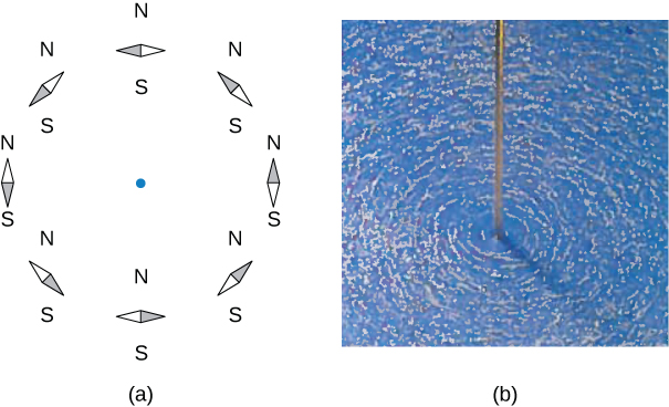
The direction of the field lines can be observed experimentally by placing several small compass needles on a circle near the wire, as illustrated in [link] . When there is no current in the wire, the needles align with Earth’s magnetic field. However, when a large current is sent through the wire, the compass needles all point tangent to the circle. Iron filings sprinkled on a horizontal surface also delineate the field lines, as shown in [link] .

Figure A shows a circle formed by the small compass needles aligned with Earth’s magnetic field. Figure B shows that iron filings sprinkled on a horizontal surface around a long wire delineate the field lines.
The shape of the magnetic field lines of a long wire can be seen using (a) small compass needles and (b) iron filings.

Calculating magnetic field due to three wires

Three wires sit at the corners of a square, all carrying currents of 2 amps into the page as shown in [link] . Calculate the magnitude of the magnetic field at the other corner of the square, point P , if the length of each side of the square is 1 cm.

Figure shows three wires I1, I2, and I3 with current flowing into the page. Wires form three corners of a square. The magnetic field is determined at the fourth corner of the square that is labeled P.
Three wires have current flowing into the page. The magnetic field is determined at the fourth corner of the square.

Strategy

The magnetic field due to each wire at the desired point is calculated. The diagonal distance is calculated using the Pythagorean theorem. Next, the direction of each magnetic field’s contribution is determined by drawing a circle centered at the point of the wire and out toward the desired point. The direction of the magnetic field contribution from that wire is tangential to the curve. Lastly, working with these vectors, the resultant is calculated.

Solution

Wires 1 and 3 both have the same magnitude of magnetic field contribution at point P :

B 1 = B 3 = μ o I 2 π R = ( 4 π × 10 −7 T m/A ) ( 2 A ) 2 π ( 0.01 m ) = 4 × 10 −5 T .

Wire 2 has a longer distance and a magnetic field contribution at point P of:

B 2 = μ o I 2 π R = ( 4 π × 10 −7 T m/A ) ( 2 A ) 2 π ( 0.01414 m ) = 3 × 10 −5 T .

The vectors for each of these magnetic field contributions are shown.

Figure shows three wires I1, I2, and I3 with current flowing into the page. Wires form three corners of a square. The magnetic field is determined at the fourth corner of the square that is labeled P. Vector B3 is directed from the point P towards the wire I1. Vector B1 is the continuation of the line from the wire I3 to the point P. Vector B2 lies between vectors B1 and B3.

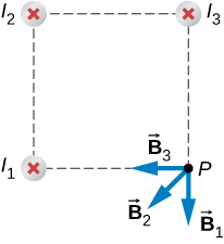
The magnetic field in the x -direction has contributions from wire 3 and the x -component of wire 2:

B net x = −4 × 10 −5 T 2.83 × 10 −5 T cos ( 45 ° ) = −6 × 10 −5 T .

The y -component is similarly the contributions from wire 1 and the y -component of wire 2:

B net y = −4 × 10 −5 T 2.83 × 10 −5 T sin ( 45 ° ) = −6 × 10 −5 T .

Therefore, the net magnetic field is the resultant of these two components:

B net = B net x 2 + B net y 2 B net = ( −6 × 10 −5 T ) 2 + ( −6 × 10 −5 T ) 2 B net = 8.48 × 10 −5 T .

Significance

The geometry in this problem results in the magnetic field contributions in the x - and y -directions having the same magnitude. This is not necessarily the case if the currents were different values or if the wires were located in different positions. Regardless of the numerical results, working on the components of the vectors will yield the resulting magnetic field at the point in need.

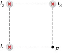
Check Your Understanding Using [link] , keeping the currents the same in wires 1 and 3, what should the current be in wire 2 to counteract the magnetic fields from wires 1 and 3 so that there is no net magnetic field at point P?

4 amps flowing out of the page

Got questions? Get instant answers now!

Summary

  • The strength of the magnetic field created by current in a long straight wire is given by B = μ 0 I 2 π R (long straight wire) where I is the current, R is the shortest distance to the wire, and the constant μ 0 = 4 π × 10 −7 T m/s is the permeability of free space.
  • The direction of the magnetic field created by a long straight wire is given by right-hand rule 2 (RHR-2): Point the thumb of the right hand in the direction of current, and the fingers curl in the direction of the magnetic field loops created by it.

Conceptual questions

How would you orient two long, straight, current-carrying wires so that there is no net magnetic force between them? ( Hint : What orientation would lead to one wire not experiencing a magnetic field from the other?)

You would make sure the currents flow perpendicular to one another.

Got questions? Get instant answers now!

Problems

A typical current in a lightning bolt is 10 4 A. Estimate the magnetic field 1 m from the bolt.

Got questions? Get instant answers now!

The magnitude of the magnetic field 50 cm from a long, thin, straight wire is 8.0 μT . What is the current through the long wire?

20 A

Got questions? Get instant answers now!

A transmission line strung 7.0 m above the ground carries a current of 500 A. What is the magnetic field on the ground directly below the wire? Compare your answer with the magnetic field of Earth.

Got questions? Get instant answers now!

A long, straight, horizontal wire carries a left-to-right current of 20 A. If the wire is placed in a uniform magnetic field of magnitude 4.0 × 10 −5 T that is directed vertically downward, what is the resultant magnitude of the magnetic field 20 cm above the wire? 20 cm below the wire?

Both answers have the magnitude of magnetic field of 4.5 × 10 −5 T .

Got questions? Get instant answers now!

The two long, parallel wires shown in the accompanying figure carry currents in the same direction. If I 1 = 10 A and I 2 = 20 A , what is the magnetic field at point P?

Got questions? Get instant answers now!

The accompanying figure shows two long, straight, horizontal wires that are parallel and a distance 2 a apart. If both wires carry current I in the same direction, (a) what is the magnetic field at P 1 ? (b) P 2 ?

Figure shows two long parallel wires that are distance 2a apart. Current flows through the wires in the same direction. Point P1 is located between the wires at a distance a from each. Point P2 is located at a distance 2 a outside the wires.

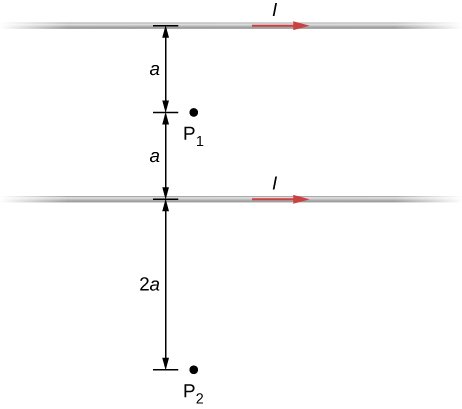
At P1, the net magnetic field is zero. At P2, B = 3 μ o I 8 π a into the page.

Got questions? Get instant answers now!

Repeat the calculations of the preceding problem with the direction of the current in the lower wire reversed.

Got questions? Get instant answers now!

Consider the area between the wires of the preceding problem. At what distance from the top wire is the net magnetic field a minimum? Assume that the currents are equal and flow in opposite directions.

The magnetic field is at a minimum at distance a from the top wire, or half-way between the wires.

Got questions? Get instant answers now!

Get Jobilize Job Search Mobile App in your pocket Now!

Get it on Google Play Download on the App Store Now


Source:  OpenStax, University physics volume 2. OpenStax CNX. Oct 06, 2016 Download for free at http://cnx.org/content/col12074/1.3
Google Play and the Google Play logo are trademarks of Google Inc.

Notification Switch

Would you like to follow the 'University physics volume 2' conversation and receive update notifications?

Ask