Observing
[link] , we can use trigonometry to determine the relationship between
,
,
and
.
As we determined from the analysis in the horizontal direction,
:
Now, we can substitute the values for
and
, into the net force equation in the vertical direction:
and
so that
and the tension is
Discussion
Note that the vertical tension in the wire acts as a normal force that supports the weight of the tightrope walker.
The tension is almost six times the 686-N weight of the tightrope walker. Since the wire is nearly horizontal, the vertical component of its tension is only a small fraction of the tension in the wire. The large horizontal components are in opposite directions and cancel, and so most of the tension in the wire is not used to support the weight of the tightrope walker.
If we wish to
create a very large tension, all we have to do is exert a force perpendicular to a flexible connector, as illustrated in
[link] . As we saw in the last example, the weight of the tightrope walker acted as a force perpendicular to the rope. We saw that the tension in the roped related to the weight of the tightrope walker in the following way:
We can extend this expression to describe the tension
created when a perpendicular force (
) is exerted at the middle of a flexible connector:
Note that
is the angle between the horizontal and the bent connector. In this case,
becomes very large as
approaches zero. Even the relatively small weight of any flexible connector will cause it to sag, since an infinite tension would result if it were horizontal (i.e.,
and
). (See
[link] .)
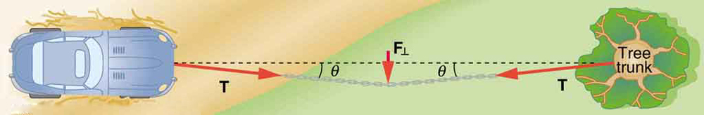
We can create a very large tension in the chain by pushing on it perpendicular to its length, as shown. Suppose we wish to pull a car out of the mud when no tow truck is available. Each time the car moves forward, the chain is tightened to keep it as nearly straight as possible. The tension in the chain is given by
; since
is small,
is very large. This situation is analogous to the tightrope walker shown in
[link] , except that the tensions shown here are those transmitted to the car and the tree rather than those acting at the point where
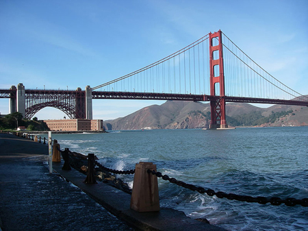
is applied.Unless an infinite tension is exerted, any flexible connector—such as the chain at the bottom of the picture—will sag under its own weight, giving a characteristic curve when the weight is evenly distributed along the length. Suspension bridges—such as the Golden Gate Bridge shown in this image—are essentially very heavy flexible connectors. The weight of the bridge is evenly distributed along the length of flexible connectors, usually cables, which take on the characteristic shape. (credit: Leaflet, Wikimedia Commons)
Extended topic: real forces and inertial frames
There is another distinction among forces in addition to the types already mentioned. Some forces are real, whereas others are not.
Real forces
are those that have some physical origin, such as the gravitational pull. Contrastingly,
fictitious forces
are those that arise simply because an observer is in an accelerating frame of reference, such as one that rotates (like a merry-go-round) or undergoes linear acceleration (like a car slowing down). For example, if a satellite is heading due north above Earth’s northern hemisphere, then to an observer on Earth it will appear to experience a force to the west that has no physical origin. Of course, what is happening here is that Earth is rotating toward the east and moves east under the satellite. In Earth’s frame this looks like a westward force on the satellite, or it can be interpreted as a violation of Newton’s first law (the law of inertia). An
inertial frame of reference is one in which all forces are real and, equivalently, one in which Newton’s laws have the simple forms given in this chapter.