

| << Chapter < Page | Chapter >> Page > |
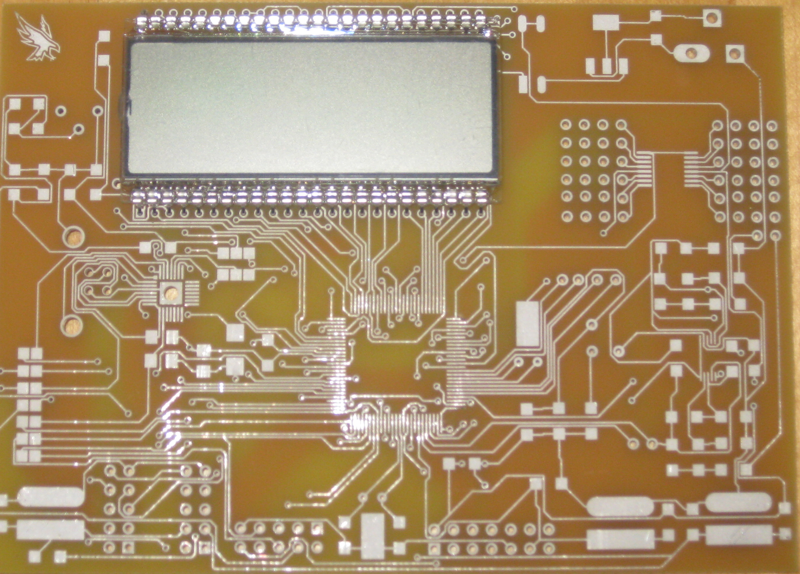
Now that the LCD is in place, flip the PCB over and solder the pins to the PCB. To do this bring the solder tip next to a pin; touch the pin with the strand of solder. The solder
sucksdown into the hole on the PCB. Figure 8 illustrates the SoftBaugh LCD mounted on the board.
The remaining components are relatively easy to mount to the PCB. In mounting the switches, it is a good idea to apply a small amount of flux to the solder pads and even tin the tips of the switches with a slight amount of solder. This makes it easier to solder the switches to the board.
The PCB for this project was designed to serve the needs of several projects at the university. Therefore, the board is populated according to the particular project. The lettering on the board identifies the surface mounted capacitors for this tutorial and Figure 9 illustrates the board with most of the essential components mounted.
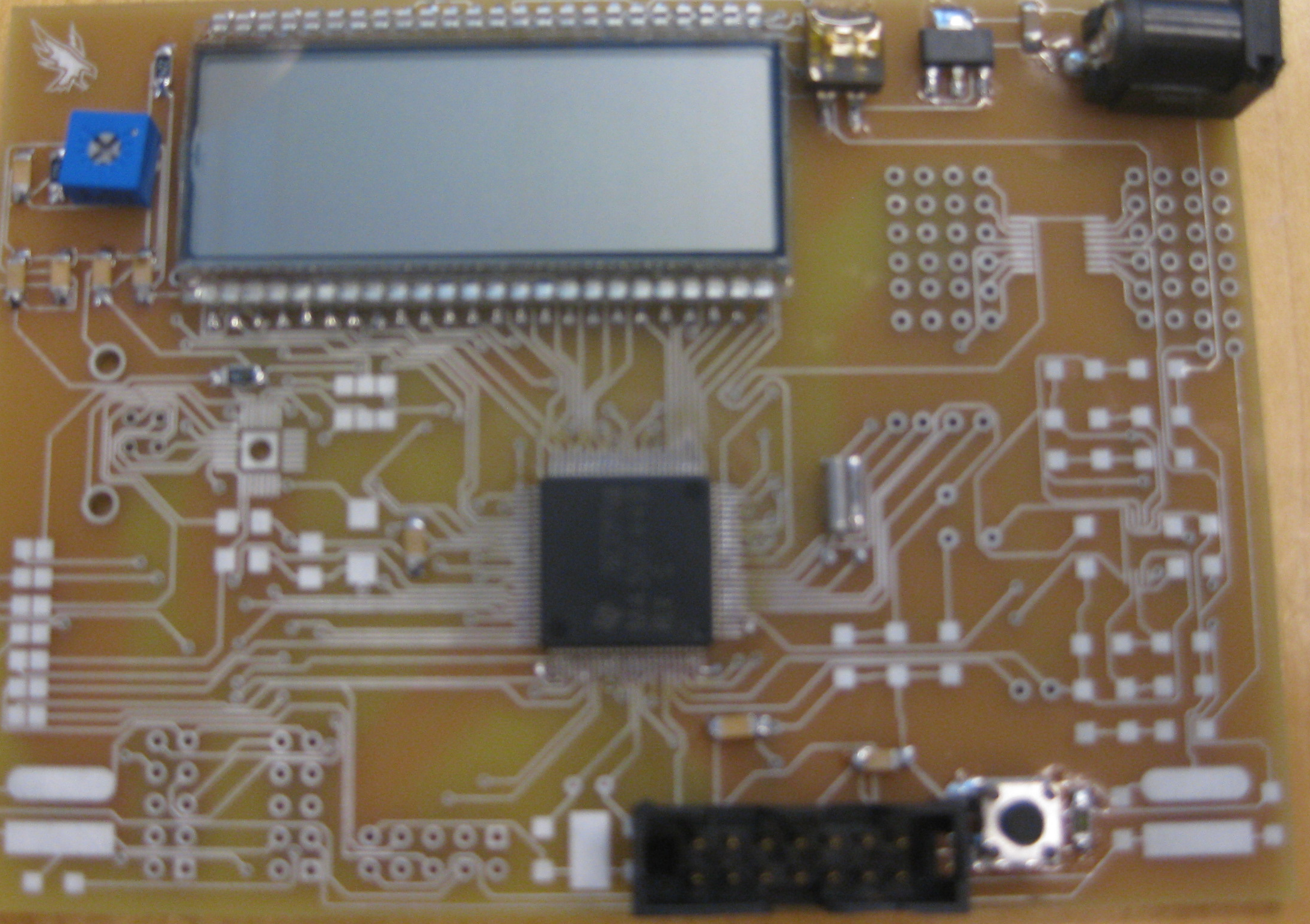
The following order is recommended for soldering components to the board. (1) The MSP430F449. (2) Surface mounted capacitors and resistors next. (3) Push button switch, voltage regulator, 5 volt input plus, slider switch. (4) Now solder in the pins of the JTAG connector. (5) Wait until last to solder in the SoftBaugh LCD.
Most all industries support students in their quest for learning about particular products from their company. Within reason, companies will provide samples of devices for students to use in their projects. There are at least two reasons that come to mind as to why they want to provide this support. First, they support education. Engineers, with good educations, are the foundation or backbone of their company. Second, if students become familiar with their products they are more likely to place orders with them during your professional career.
This is the micro computer that is utilized in this tutorial. Samples will be provided to students enrolled in the course. The following Texas Instrument URL is where you can order a 3-lot sample of the MSP430F449. Just follow the instructions. Be sure to give a mailing address where UPS/FedEx or order delivery services can deliver a package to you. You cannot use P.0.Boxes. In filling out the request form for parts indicate as necessary that you are a student working on an embedded microcomputer project.
(External Link)
After you have constructed your board and you know that you can flash a message to the LCD, the next part is for you to select a sensor for application with the PCB you have built. In particular, you are to connect the output voltage from a sensor you select to an input port to the Analog to Digital converter of the MSP 430. You might select a temperature sensor, a force sensor, a magnetic field measurement sensor and so on. The choice of sensor is left up to you. However, you must find a sensor you want to use and you must order free samples.
Notification Switch
Would you like to follow the 'Eel3111 force sensor group july 2010' conversation and receive update notifications?

|
|

|
|

|
|

|
|

|
|
|
|
|

|
|

|
|

|
|

|