

| << Chapter < Page | Chapter >> Page > |
With all the connect points of the MSP 430 on top of the corresponding PCB pads, hold things in place and use the soldering iron to tack a connect point of the chip to a trace at pins 25 and 1 as shown above. DO NOT ADD ANY SOLDER TO THE TIP OF THE SOLDERING IRON! Set things up as shown in Figure 5. Apply a touch of flux to the tip of each microchip pin.
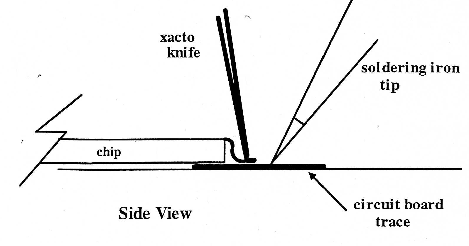
At pin 25, shown in Figure 6, continue to hold the chip in place. Place the tip of the soldering iron on the circuit trace as shown above. The solder on the trace will melt. This should temporarily tack the circuit connect point to the trace. Allow the solder joint to cool for about 5 seconds. Continue to hold the chip in place. Move to another corner point on the chip (pin 1) and repeat the above process. At this point the chip should be tacked to the traces and lined up properly. Now move to another connect point (pin 24) and place the tip of an exacto knife on top of the chip connect point as shown in Figure 7. Apply the tip of the soldering iron to the corresponding circuit trace and allowing the solder on the trace to flow. Place the tip of the xacto knife on top of the connect point to the board; remove the soldering iron tip and apply a small pressure (with the xacto knife) to hold the connect point down; allow the junction to cool for a few seconds.
Then, the above process is continued by moving around the board. A good idea is to pin down connect pin 2 then move to pin 23. This allows connect point at pin 2 to cool for a few seconds before coming back to solder at pin 23 and so on. If at some point there does not seem to be enough solder on the traces to bond to the connect point, try placing the soldering iron tip in the tinning paste. Clean on the sponge. There is usually a slight amount of solder left on the tip. This can be used to add a little solder to the trace.
After soldering all the pins to the board, the user should check the connections. A good way to do this is to place the tip of your xacto blade to the edge of each pin. Apply a slight amount of pressure to the pin. If the pin moves you know you have a faulty solder connection. Clean and flux the tip of the soldering iron two or three times and then proceed to Re-do the solder joint.
The SoftBaugh LCD display unit has 24 pins on each side. The following procedure establishes one manner in which to mount the unit to the board.
To begin with, the small notch at one end of the LCD should be on the left side when lining up pins on the board. Place the pins on one side of the unit over the corresponding holes on the board. Slightly jiggle the unit until you can get the one side to slide into the holes. There are times when slightly jiggling the unit will result in both sides of the LCD to smoothly slide into the holes of the board. However if this is not the case, do not try to force the pins into the holes. It is fairly easy to get one side of the unit to go into the board. Where the pins emerge from the bottom of the board, keep the tips about flush with the board. Then attempt to line things up with the other side of the LCD. Start at one end and use the tip of a xacto knife to move each pin over the corresponding hole. Continue to move down the pin line and line up the pins with the holes. Once the pins have lined up, the second side will fit in place. Push the LCD in place with the pins protruding from the back of the board.
Notification Switch
Would you like to follow the 'Eel3111 force sensor group july 2010' conversation and receive update notifications?

|
|

|
|

|
|

|
|

|
|

|
|

|
|

|
|

|
|

|