

| << Chapter < Page | Chapter >> Page > |
Table 1 shows a list of parts that are needed to carry out the main objectives in the student tutorial. Be sure to take an inventory of the items listed in Table 1.
There are soldering stations and microscopes available to accomplish the student tutorial. A microscope is necessary to see how to do the soldering work. This will be realized as practice in soldering is done often and over time. Solder and flux are provided with the soldering stations.
The student is expected to solder two surface mounted 0.1 uF capacitors to the printed circuit board. In addition, the user is expected to solder all 100 pins of the MSP 430F449 package to the printed circuit board.
| Item # | Description (Digikey) | Quantity |
| 1 | MHC14K-ND: JTAG Connector | 1 |
| 2 | EG1868CT-ND: Push Button Switch | 1 |
| 3 | CP-102A-ND: Power Connector | 1 |
| 4 | LM2937IMP-3.3CT ND: Voltage Regulator | 1 |
| 5 | CT2192MST-ND: Switch 2 position | 1 |
| 6 | 300-1001-ND: 32.7 kHz Crystal | 1 |
| 7 | 399-1249-1-ND: 0.1uF SMD capacitor | 3 |
| 8 | 399-1296-1–ND: 1uF SMD capacitor | 1 |
| 9 | 311-47kECT-ND: 100 kohm resistor | 2 |
| 10 | SBLCDA2: LCD Display | 1 |
| 11 | circuit board - no mask - practice soldering | 1 |
| 12 | circuit board - with mask - final product | 1 |
| 13 | miscellaneous 24 gauge wire | 2 |
| 14 | TI MSP430F449IPZ chip | 1 |
Avoid breathing the fumes from the solder. The solder is rosin core with a certain percentage of lead (about 2%). It is not healthy to breathe these fumes. Read the label on the soldering tube provided with the soldering station and use the precautions given on the label.
Set the temperature of the soldering station to 800 F. After the tip has reached this temperature, dip the tip of the iron into the tinning paste. Clean the tip with the sponge that comes with the station (add water to the sponge). After this step you may want to take a knife blade and lightly scrape the tip of the iron. Repeat dipping the tip in the tinning past and cleaning the tip on the sponge until the lower 1/4 inch of the tip is
silvered.A clean silvered tip is the first indication that the tool has passed the first necessary step toward being properly tinned. Next, touch a strand of solder to the tip. If the solder balls up and drops from the tip, then the tip is not properly tinned. Repeat the above steps until the solder will stick to the tip. At that point the tip is properly tinned and ready for use. Another thing; when you are through soldering, always clean the tip before turning off the station. You might want to take the edge of a knife blade and lightly scrape the tip. Be careful when using the soldering iron. Soldering iron burns hurt! So does melted solder that splashes on you!
Figure 1 illustrates a top view representation of the PCB utilized to mount the MSP430F449 and the SoftBaugh LCD among other components.

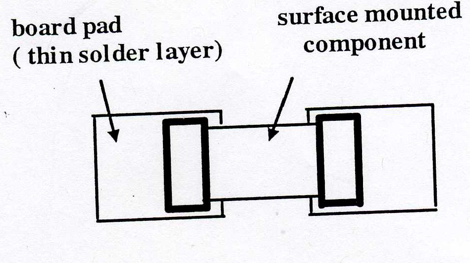
Now consider soldering a surface mounted (SMD) device such as the MSP430F449, a resistor or capacitor to a board. The PCB has a solder pad or tab for each end of the SMD pads to rest. This is indicated in Figure 2.
Notification Switch
Would you like to follow the 'Eel3111 force sensor group july 2010' conversation and receive update notifications?

|
|

|
|

|
|

|
|

|
|

|
|

|
|

|
|

|
|

|