

| << Chapter < Page | Chapter >> Page > |
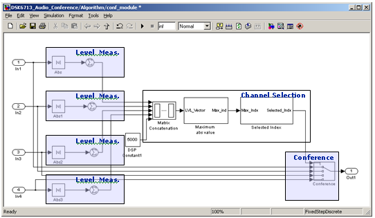
For each frame the counter correspondent to the loudest channel is incremented. When a channel counter equals a threshold The requirement for a threshold amount of wining rounds was set in order to prevent random noise or occasional “spikes” from interfering with the algorithms function. This threshold is configurable. In this example it was set to 10. , the correspondent channel is selected.
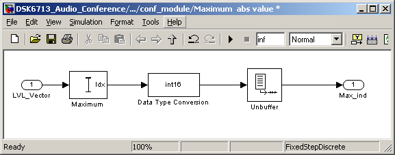
For Each 64 samples frame the following algorithm is implemented:
This section will describe the process of generating a real-time application using Simulink blocks for the algorithm itself and the driver introduced in the previous chapter. The Simulink model is shown in Figure 21 The algorithm is implemented for 4 channels, however we will use only three of them. .
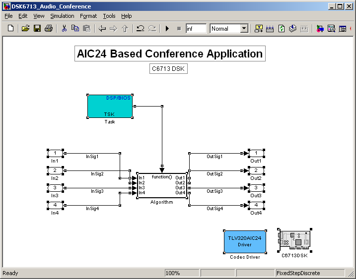
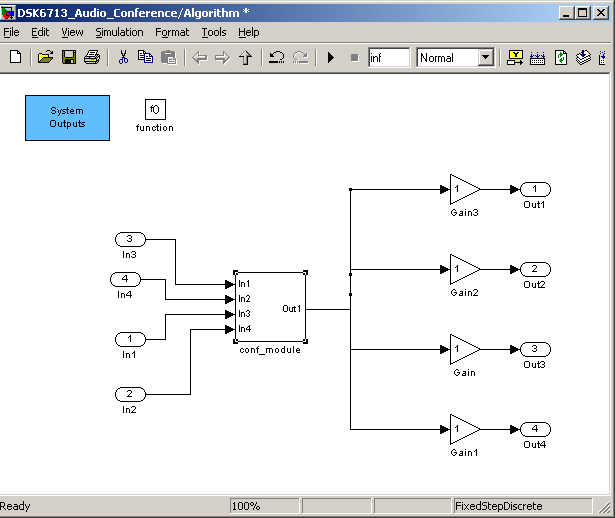
The block diagram shown in Figure 20 is translated to the model shown in the following figures.
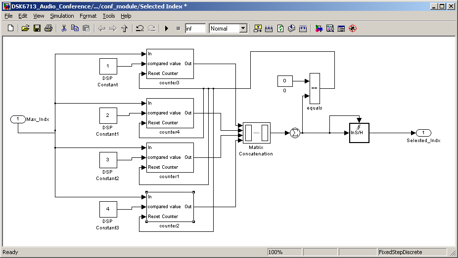
The real-time model can be found in the file C67_Simulink_conference.rar.
MATLAB and Simulink are registered trademarks of The MathWorks, Inc. See www.mathworks.com/trademarks for a list of additional trademarks. Other product or brand names may be trademarks or registered trademarks of their respective holders.
The following table is based on the one the Codec’s EVM Datasheet.
It matches the board connectors with the inputs and outputs.
(Notice, this table includes corrections and elaborations in compare to the one in the Datasheet).
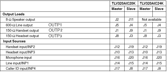
The Inputs and Outputs of a certain channel are set by its 6a and 6b registers.
Those registers can be set, like before, between the initialization of the Handle and its activation.
If, for example, the input samples of channel 0 in the CODEC should be received from INP3 According to the table the connection is to J10, since we are working with 24K EVM and channel 0 is located at the master side.) . The configuration should be as follows:
Notification Switch
Would you like to follow the 'From matlab and simulink to real-time with ti dsp's' conversation and receive update notifications?

|
|
|
|
|
|

|
|

|
|

|
|

|
|

|
|

|
|
|
|