

| << Chapter < Page | Chapter >> Page > |
There are a number of companies that manufacture sensors. One company is Analog Devices. Their web address is (External Link) . Other companies such as Texas Instruments and Freescale also provide sample sensors.
The software required for this tutorial is available on the TI website to download for free. The web address to obtain the software is:
(External Link)
You will find the software from both IAR and TI that supports the Flash Emulation Tool. You are encouraged to spend some time looking over this material.
We now explain how to use the above tool to exercise the embedded processor board so that that the LCD displays a count from A-Z.
First connect the 25-pin cable connecter of the FET to the printer port of your PC. Connect the 14-pin connector to the JTAG port on your board. Be sure this cable is connected in the
Upposition. This is illustrated in Figure 10.

Step 1 : On your PC create the following directory: C:\430project\software. The files required to implement this student tutorial for the MSP430F449 will be given by the instructor. Once given, copy the files to your Computer. These files may include: lcd.c, lcd.h, lcddemo.c.
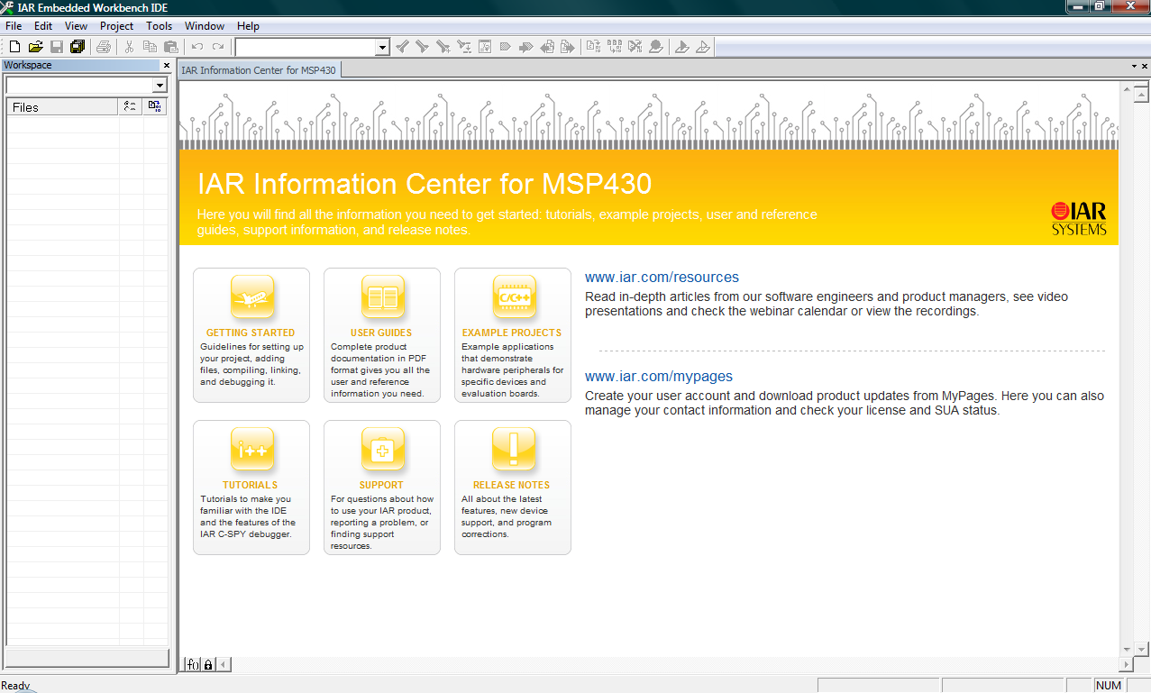
Step 2 : Take the following path on your PC: Start / Programs / IAR Systems/ IAR Embedded Workbench for MSP430 KickStart/IAR / Embedded Workbench . This will open the screen shown in Figure 11.
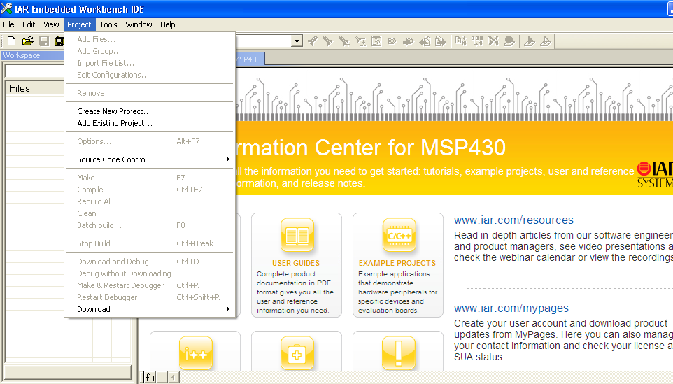
Step 3 : Now click on Project/Create New Project… and you will see the screen shown in Figure 12.
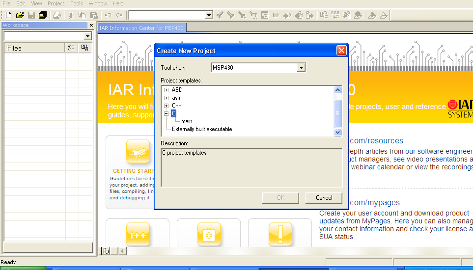
Step 4 : Now double click on the programming language you will be using for the project and click on main. This step is shown in Figure 13. A Save As dialog box appears. Choose a name to save your project under.
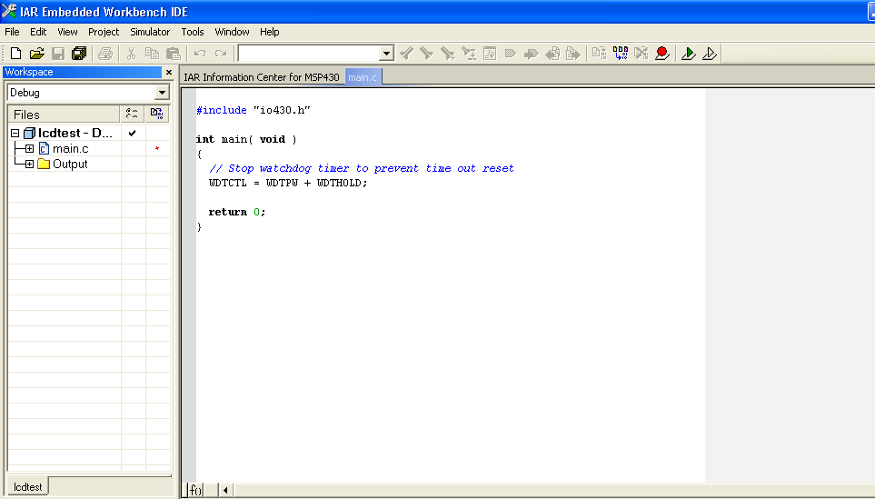
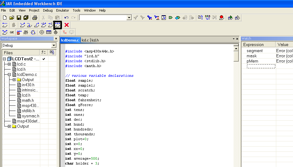
Step 5 : Once you’ve created your project, this will produce the screen shown in Figure 14.
Step 6 : Now click on Project/Options… Under category, highlight general options and select which device you will be using for the project. The screen shown in Figure 15 illustrates this step.
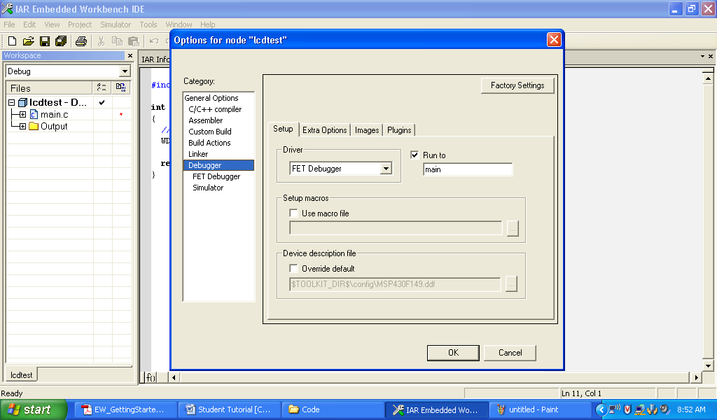
Step 7 : From the screen in Figure 15, under category highlight Debugger and choose the FET Debugger as your driver. This will produce the screen shown in Figure 16.
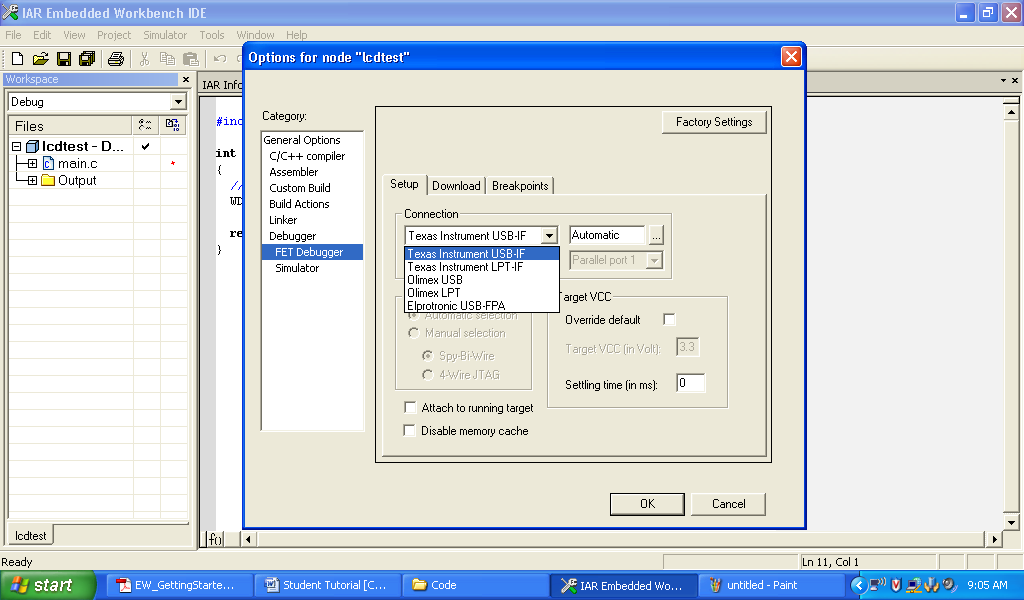
Step 8 : Now under category highlight FET Debugger . Choose your connection whether it is USB or not. This is shown in the screen in Figure 17.
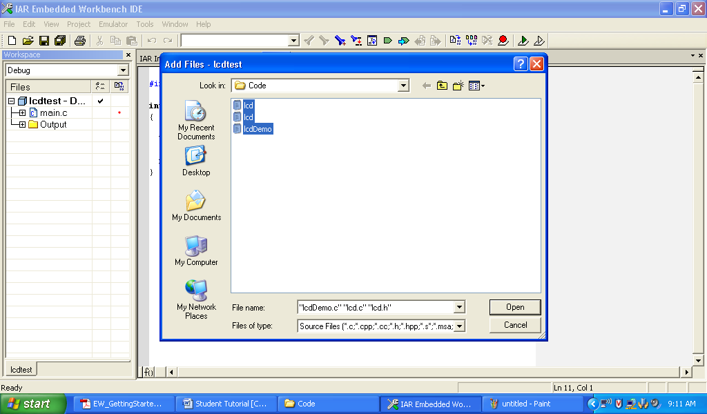
Step 9 : To add the project files, click on Project/Add Files . Highlight all the files needed for the project and click Open . The files will then be added to your workspace. This is illustrated in the screen shown in Figure 18.
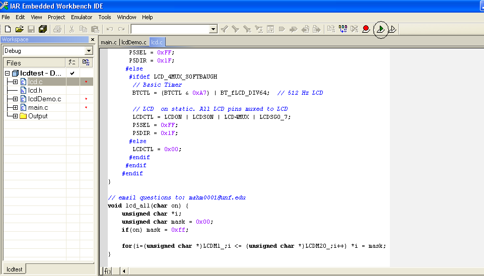
Step 10 : Once the files are downloaded, click on the arrow on the top right screen of your window which means you are ready to download and debug your project. This is shown in Figure 19.
Step 11 : After building your project, the debugger window opens at the bottom part of your screen. Click on the three arrows encircled in Figure 20 to run the program.
Step 12 : Provided that the FET cable is inserted to your PC printer port and the JTAG plug on your processor board
and provided you have built your board correctly, you will see the screen go through a stage of showing that the board is being erased and then show it being programmed. After the programming stage is complete you should see some a count from A-Z scroll across the LCD.

The following specifies the pin-out connections of the MSP430F449 Texas Instrument Mixed Signal Micro controller. Also, a general outline of the physical package is included. For more data on the device, check the following web site.
(External Link)
Look under technical documents/data sheets.

The University of North Florida (UNF) EE team began using the TI MSP430F449 a number of years ago. Bethune-Cookman University and the University of Tennessee (UT) adopted UNF’s lab kits into their curriculum. Dr. Walter Green, UT Electrical Engineering, had his students prepare a users guide for the lab. UNF students adopted the UT user’s guide and updated it per UNF current embedded system design activities. UNF thanks UT for their help and contribution to this users guide.
Notification Switch
Would you like to follow the 'Eel3111 force sensor group july 2010' conversation and receive update notifications?

|
|

|
|

|
|

|
|

|
|
|
|
|

|
|

|
|

|
|
|
|