

| << Chapter < Page | Chapter >> Page > |
The study of electrical circuits is essential to understand the technology that uses electricity in the real-world. This includes electricity being used for the operation of electronic devices like computers.
Aim:
In this experiment we will look at the relationship between the current going through a resistor and the potential difference (voltage) across the same resistor.
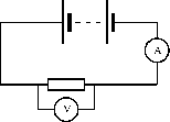
Method:
| Voltage, (V) | Current, (A) |
| 1,5 | |
| 3,0 | |
| 4,5 | |
| 6,0 |
Results:
If you do not have access to the equipment necessary for the Ohm's Law experiment, you can do this activity.
| Voltage, (V) | Current, (A) |
| 3,0 | 0,4 |
| 6,0 | 0,8 |
| 9,0 | 1,2 |
| 12,0 | 1,6 |
Conclusions:
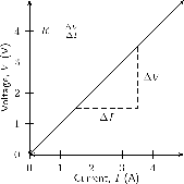
An important relationship between the current, voltage and resistance in a circuit was discovered by Georg Simon Ohm and is called Ohm's Law .
The amount of electric current through a metal conductor, at a constant temperature, in a circuit is proportional to the voltage across the conductor. Mathematically, Ohm's Law is written:
Ohm's Law tells us that if a conductor is at a constant temperature, the current flowing through the conductor is proportional to the voltage across it. This means that if we plot voltage on the -axis of a graph and current on the -axis of the graph, we will get a straight-line. The gradient of the straight-line graph is related to the resistance of the conductor.
Phet simulation for ohm's law
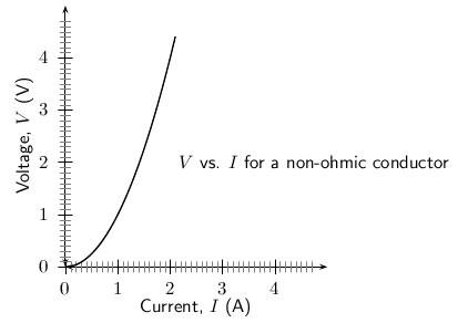
As you have seen, there is a mention of constant temperature when we talk about Ohm's Law. This is because the resistance of some conductors changes as their temperature changes. These types of conductors are called non-ohmic conductors, because they do not obey Ohm's Law. As can be expected, the conductors that obey Ohm's Law are called ohmic conductors. A light bulb is a common example of a non-ohmic conductor. Nichrome wire is an ohmic conductor.
In a light bulb, the resistance of the filament wire will increase dramatically as it warms from room temperature to operating temperature. If we increase the supply voltage in a real lamp circuit, the resulting increase in current causes the filament to increase in temperature, which increases its resistance. This effectively limits the increase in current. In this case, voltage and current do not obey Ohm's Law.
The phenomenon of resistance changing with variations in temperature is one shared by almost all metals, of which most wires are made. For most applications, these changes in resistance are small enough to be ignored. In the application of metal lamp filaments, which increase a lot in temperature (up to about 1000 C, and starting from room temperature) the change is quite large.
In general non-ohmic conductors have plots of voltage against current that are curved, indicating that the resistance is not constant over all values of voltage and current.
Repeat the experiment as decribed in the previous section. In this case use a light bulb as a resistor. Compare your results to the ohmic resistor.
We are now ready to see how Ohm's Law is used to analyse circuits.
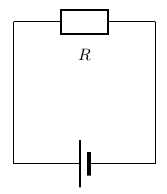
Consider the circuit with an ohmic resistor, . If the resistor has a resistance of 5 and voltage across the resistor is 5 V, then we can use Ohm's law to calculate the current flowing through the resistor.
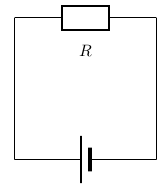
Ohm's law is:
which can be rearranged to:
The current flowing through the resistor is:
The resistance of the above resistor is 10 and the current going through the resistor is 4 A. What is the potential difference (voltage) across the resistor?
It is an Ohm's Law problem. So we use the equation:
The voltage across the resistor is 40 V.
Notification Switch
Would you like to follow the 'Siyavula textbooks: grade 11 physical science' conversation and receive update notifications?

|
|

|
|

|
|

|
|

|
|

|
|

|
|
|
|
|

|
|
|
|