<< Chapter < Page Chapter >> Page >
  • Sketch voltage and current versus time in simple inductive, capacitive, and resistive circuits.
  • Calculate inductive and capacitive reactance.
  • Calculate current and/or voltage in simple inductive, capacitive, and resistive circuits.

Many circuits also contain capacitors and inductors, in addition to resistors and an AC voltage source. We have seen how capacitors and inductors respond to DC voltage when it is switched on and off. We will now explore how inductors and capacitors react to sinusoidal AC voltage.

Inductors and inductive reactance

Suppose an inductor is connected directly to an AC voltage source, as shown in [link] . It is reasonable to assume negligible resistance, since in practice we can make the resistance of an inductor so small that it has a negligible effect on the circuit. Also shown is a graph of voltage and current as functions of time.

Part a of the figure describes an A C voltage source V connected across an inductor L. The voltage across the inductance is shown as V L. Part b of the figure describes a graph showing the variation of current and voltage across the inductance as a function of time. The voltage V L and current I L is plotted along the Y axis and the time t is along the X axis. The graph for current is a progressive sine wave from the origin. The graph for voltage V is a cosine wave and an amplitude slightly less than the current wave.
(a) An AC voltage source in series with an inductor having negligible resistance. (b) Graph of current and voltage across the inductor as functions of time.

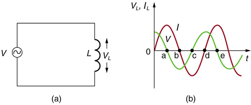
The graph in [link] (b) starts with voltage at a maximum. Note that the current starts at zero and rises to its peak after the voltage that drives it, just as was the case when DC voltage was switched on in the preceding section. When the voltage becomes negative at point a, the current begins to decrease; it becomes zero at point b, where voltage is its most negative. The current then becomes negative, again following the voltage. The voltage becomes positive at point c and begins to make the current less negative. At point d, the current goes through zero just as the voltage reaches its positive peak to start another cycle. This behavior is summarized as follows:

Ac voltage in an inductor

When a sinusoidal voltage is applied to an inductor, the voltage leads the current by one-fourth of a cycle, or by a 90º phase angle.

Current lags behind voltage, since inductors oppose change in current. Changing current induces a back emf V = L ( Δ I / Δ t ) size 12{V= - L \( ΔI/Δt \) } {} . This is considered to be an effective resistance of the inductor to AC. The rms current I size 12{I} {} through an inductor L size 12{L} {} is given by a version of Ohm’s law:

I = V X L , size 12{I= { {V} over {X rSub { size 8{L} } } } } {}

where V is the rms voltage across the inductor and X L size 12{X rSub { size 8{L} } } {} is defined to be

X L = fL , size 12{X rSub { size 8{L} } =2π ital "fL"} {}

with f size 12{f} {} the frequency of the AC voltage source in hertz (An analysis of the circuit using Kirchhoff’s loop rule and calculus actually produces this expression). X L size 12{X rSub { size 8{L} } } {} is called the inductive reactance    , because the inductor reacts to impede the current. X L size 12{X rSub { size 8{L} } } {} has units of ohms ( 1 H = 1 Ω s , so that frequency times inductance has units of ( cycles/s ) ( Ω s ) = Ω size 12{ \( "cycles/s" \) \( ` %OMEGA cdot s \) = %OMEGA } {} ), consistent with its role as an effective resistance. It makes sense that X L size 12{X rSub { size 8{L} } } {} is proportional to L size 12{L} {} , since the greater the induction the greater its resistance to change. It is also reasonable that X L size 12{X rSub { size 8{L} } } {} is proportional to frequency f size 12{f} {} , since greater frequency means greater change in current. That is, Δ I t size 12{ΔI} {} is large for large frequencies (large f size 12{f} {} , small Δ t size 12{Δt} {} ). The greater the change, the greater the opposition of an inductor.

Calculating inductive reactance and then current

(a) Calculate the inductive reactance of a 3.00 mH inductor when 60.0 Hz and 10.0 kHz AC voltages are applied. (b) What is the rms current at each frequency if the applied rms voltage is 120 V?

Strategy

The inductive reactance is found directly from the expression X L = fL size 12{X rSub { size 8{L} } =2π ital "fL"} {} . Once X L size 12{X rSub { size 8{L} } } {} has been found at each frequency, Ohm’s law as stated in the Equation I = V / X L size 12{I=V/X rSub { size 8{L} } } {} can be used to find the current at each frequency.

Solution for (a)

Entering the frequency and inductance into Equation X L = fL size 12{X rSub { size 8{L} } =2π ital "fL"} {} gives

X L = fL = 6.28 ( 60.0 / s ) ( 3.00 mH ) = 1.13 Ω at 60 Hz .

Similarly, at 10 kHz,

X L = fL = 6 . 28 ( 1.00 × 10 4 /s ) ( 3 . 00 mH ) = 188 Ω at 10 kHz . size 12{X rSub { size 8{L} } =2π ital "fL"=6 "." "28" \( 3 "." "00"" mH" \) ="188" %OMEGA } {}

Solution for (b)

The rms current is now found using the version of Ohm’s law in Equation I = V / X L size 12{I=V/X rSub { size 8{L} } } {} , given the applied rms voltage is 120 V. For the first frequency, this yields

I = V X L = 120 V 1.13 Ω = 106 A at 60 Hz .

Similarly, at 10 kHz,

I = V X L = 120 V 188 Ω = 0.637 A at 10 kHz . size 12{I= { {V} over {X rSub { size 8{L} } } } = { {"120"" V"} over {"188 " %OMEGA } } =0 "." "637"" A"} {}

Discussion

The inductor reacts very differently at the two different frequencies. At the higher frequency, its reactance is large and the current is small, consistent with how an inductor impedes rapid change. Thus high frequencies are impeded the most. Inductors can be used to filter out high frequencies; for example, a large inductor can be put in series with a sound reproduction system or in series with your home computer to reduce high-frequency sound output from your speakers or high-frequency power spikes into your computer.

Got questions? Get instant answers now!

Questions & Answers

calculate molarity of NaOH solution when 25.0ml of NaOH titrated with 27.2ml of 0.2m H2SO4
Gasin Reply
what's Thermochemistry
rhoda Reply
the study of the heat energy which is associated with chemical reactions
Kaddija
How was CH4 and o2 was able to produce (Co2)and (H2o
Edafe Reply
explain please
Victory
First twenty elements with their valences
Martine Reply
what is chemistry
asue Reply
what is atom
asue
what is the best way to define periodic table for jamb
Damilola Reply
what is the change of matter from one state to another
Elijah Reply
what is isolation of organic compounds
IKyernum Reply
what is atomic radius
ThankGod Reply
Read Chapter 6, section 5
Dr
Read Chapter 6, section 5
Kareem
Atomic radius is the radius of the atom and is also called the orbital radius
Kareem
atomic radius is the distance between the nucleus of an atom and its valence shell
Amos
Read Chapter 6, section 5
paulino
Bohr's model of the theory atom
Ayom Reply
is there a question?
Dr
when a gas is compressed why it becomes hot?
ATOMIC
It has no oxygen then
Goldyei
read the chapter on thermochemistry...the sections on "PV" work and the First Law of Thermodynamics should help..
Dr
Which element react with water
Mukthar Reply
Mgo
Ibeh
an increase in the pressure of a gas results in the decrease of its
Valentina Reply
definition of the periodic table
Cosmos Reply
What is the lkenes
Da Reply
what were atoms composed of?
Moses Reply
Got questions? Join the online conversation and get instant answers!
Jobilize.com Reply
Practice Key Terms 2

Get Jobilize Job Search Mobile App in your pocket Now!

Get it on Google Play Download on the App Store Now


Source:  OpenStax, College physics. OpenStax CNX. Jul 27, 2015 Download for free at http://legacy.cnx.org/content/col11406/1.9
Google Play and the Google Play logo are trademarks of Google Inc.

Notification Switch

Would you like to follow the 'College physics' conversation and receive update notifications?

Ask