<< Chapter < Page Chapter >> Page >

For this question, consider the circuit shown in the following figure.

Circuit that across the top from left to right goes point b, battery with voltage E1, point c, resistor with resistance r1, and point d; across the middle goes point a, battery with voltage E2, point k, resistor with resistance r2, point l, resistor with resistance R2, and point e; across the bottom goes point j, battery with voltage E3, point i, resistor with resistance r3, and point h; along the left side from top to bottom goes a resistor with resistance R1, point a, and a resistor with resistance R3; and along the right side goes a resistor with resistance R5, point e, a resistor with resistance r4, point f, a battery with voltage E4, and point g. Additionally, there are three arrows showing the direction of the current: one between point a and the resistor with resistance R1 pointing up; another between point a and the battery with voltage E2 pointing right; and another between point j and the resistor with resistance R3 pointing up.
  1. Assuming that none of the three currents ( I 1 , I 2 , and I 3 ) are equal to zero, which of the following statements is false?

    1. I 3 = I 1 + I 2 at point a .
    2. I 2 = I 3 - I 1 at point e .
    3. The current through R 3 is equal to the current through R 5.
    4. The current through R 1 is equal to the current through R 5.
  2. Which of the following statements is true?

    1. E 1 + E 2 + I 1 R 1 - I 2 R 2 + I 1 r 1 - I 2 r 2 + I 1 R 5 = 0
    2. - E 1 + E 2 + I 1 R 1 - I 2 R 2 + I 1 r 1 - I 2 r 2 - I 1 R 5 = 0
    3. E 1 - E 2 - I 1 R 1 + I 2 R 2 - I 1 r 1 + I 2 r 2 - I 1 R 5 = 0
    4. E 1 + E 2 - I 1 R 1 + I 2 R 2 - I 1 r 1 + I 2 r 2 + I 1 R 5 = 0
  3. If I 1 = 5 A and I 3 = -2 A, which of the following statements is false?

    1. The current through R 1 will flow from a to b and will be equal to 5 A.
    2. The current through R 3 will flow from a to j and will be equal to 2 A.
    3. The current through R 5 will flow from d to e and will be equal to 5 A.
    4. None of the above.
  4. If I 1 = 5 A and I 3 = -2 A, I 2 will be equal to

    1. 3 A
    2. -3 A
    3. 7 A
    4. -7 A

a. (c)

b. (c)

c. (d)

d. (d)

Got questions? Get instant answers now!
A circuit with nothing on the top or bottom, but a battery marked E on the left, a resistor marked R1 in the middle, and a resistor marked R2 on the right.

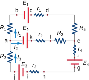
In an experiment this circuit is set up. Three ammeters are used to record the currents in the three vertical branches (with R 1 , R 2 , and E) . The readings of the ammeters in the resistor branches (i.e. currents in R 1 and R 2 ) are 2 A and 3 A respectively.

  1. Find the equation obtained by applying Kirchhoff’s loop rule in the loop involving R 1 and R 2 .
  2. What will be the reading of the third ammeter (i.e. the branch with E )? If E were replaced by 3 E , how would this reading change?
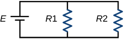
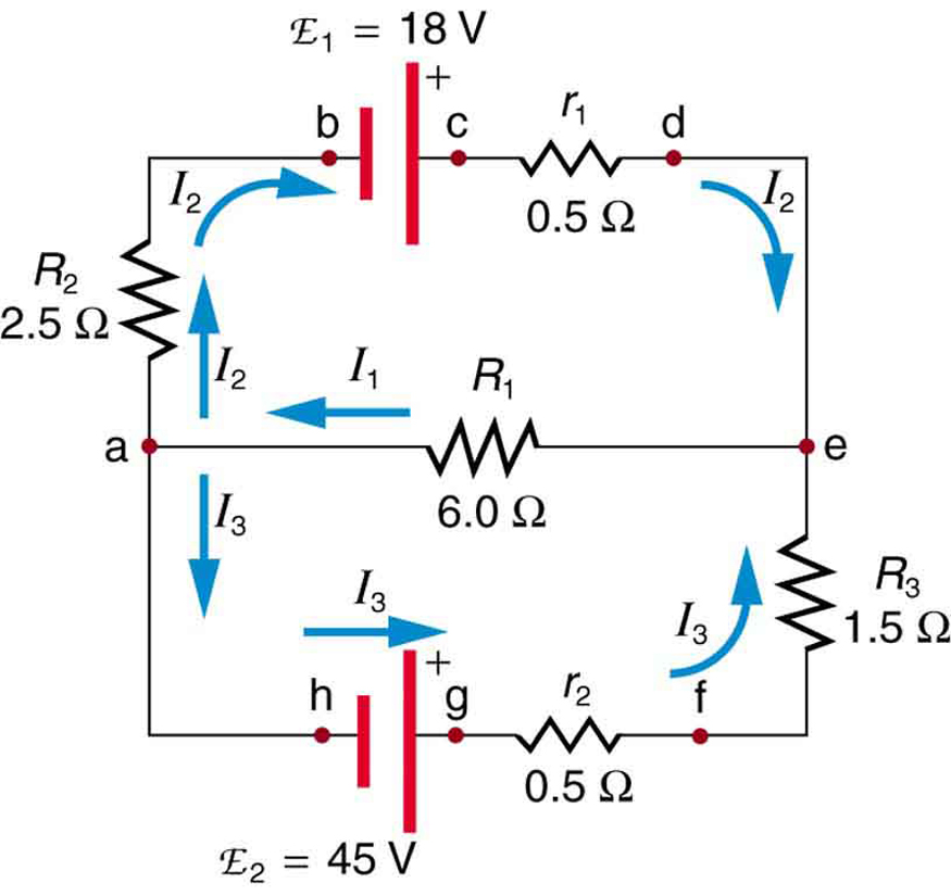
  3. If the original circuit is modified by adding another voltage source (as shown in the following circuit), find the readings of the three ammeters.
A circuit a battery marked E on the left, a resistor marked R1 in the middle, and a resistor marked R2 on the right. There is nothing on the bottom, and on the top, there is a battery marked 2E between the two resistors.
Got questions? Get instant answers now!
Circuit with a battery with voltage E1 and resistor with resistance r1 across the top from left to right; point A, a resistor with resistance R1, and point B across the middle; and a battery marked E2 and a resistor with resistance r2 across the bottom. Additionally, on the left, from top to bottom there is a resistor with resistance R2 and point A; on the right, from top to bottom there is point B and a resistor with resistance R3.

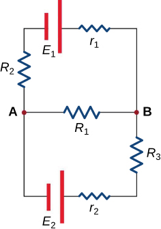
In this circuit, assume the currents through R 1 , R 2 and R 3 are I 1 , I 2 and I 3 respectively and all are flowing in the clockwise direction.

  1. Find the equation obtained by applying Kirchhoff’s junction rule at point A.
  2. Find the equations obtained by applying Kirchhoff’s loop rule in the upper and lower loops.
  3. Assume R 1 = R 2 = 6 Ω, R 3 = 12 Ω, r 1 = r 2 = 0 Ω, E 1 = 6 V and E 2 = 4 V. Calculate I 1 , I 2 and I 3 .
  4. For the situation in which E 2 is replaced by a closed switch, repeat parts (a) and (b). Using the values for R 1 , R 2 , R 3 , r 1 and E 1 from part (c) calculate the currents through the three resistors.
  5. For the circuit in part (d) calculate the output power of the voltage source and across all the resistors. Examine if energy is conserved in the circuit.
  6. A student implemented the circuit of part (d) in the lab and measured the current though one of the resistors as 0.19 A. According to the results calculated in part (d) identify the resistor(s). Justify any difference in measured and calculated value.
  1. I 1 + I 3 = I 2
  2. E 1 - I 1 R 1 - I 2 R 2 - I 1 r 1 = 0; - E 2 + I 1 R 1 - I 3 R 3 - I 3 r 2 = 0
  3. I 1 = 8/15 A, I 2 = 7/15 A and I 3 = - 1/15 A
  4. I 1 = 2/5 A, I 2 = 3/5 A and I 3 = 1/5 A
  5. P E1 = 18/5 W and P R1 = 24/25 W, P R2 = 54/25 W, P R3 = 12/25 W. Yes, P E1 = P R1 + P R2 + P R3
  6. R 3, losses in the circuit
Got questions? Get instant answers now!

Section summary

  • Kirchhoff’s rules can be used to analyze any circuit, simple or complex.
  • Kirchhoff’s first rule—the junction rule: The sum of all currents entering a junction must equal the sum of all currents leaving the junction.
  • Kirchhoff’s second rule—the loop rule: The algebraic sum of changes in potential around any closed circuit path (loop) must be zero.
  • The two rules are based, respectively, on the laws of conservation of charge and energy.
  • When calculating potential and current using Kirchhoff’s rules, a set of conventions must be followed for determining the correct signs of various terms.
  • The simpler series and parallel rules are special cases of Kirchhoff’s rules.

Conceptual questions

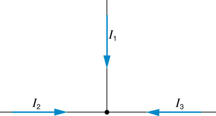
Can all of the currents going into the junction in [link] be positive? Explain.

Got questions? Get instant answers now!
The diagram shows a T junction with currents I sub one, I sub two, and I sub three entering the T junction.

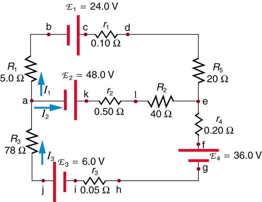
Apply the junction rule to junction b in [link] . Is any new information gained by applying the junction rule at e? (In the figure, each emf is represented by script E.)

Got questions? Get instant answers now!
The diagram shows a complex circuit with four voltage sources: E sub one, E sub two, E sub three, E sub four and several resistive loads, wired in two loops and two junctions. Several points on the diagram are marked with letters a through g. The current in each branch is labeled separately.

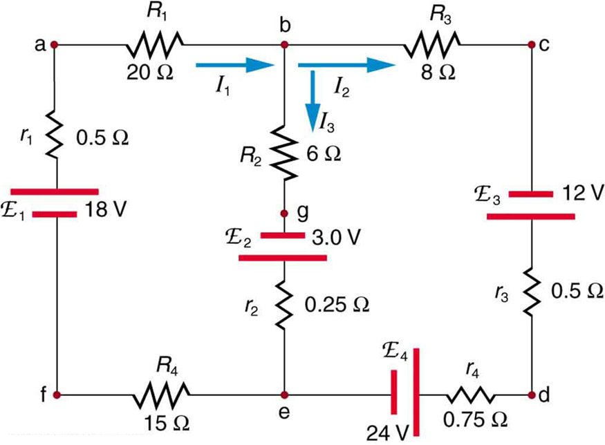
(a) What is the potential difference going from point a to point b in [link] ? (b) What is the potential difference going from c to b? (c) From e to g? (d) From e to d?

Got questions? Get instant answers now!

Apply the loop rule to loop afedcba in [link] .

Got questions? Get instant answers now!

Apply the loop rule to loops abgefa and cbgedc in [link] .

Got questions? Get instant answers now!

Problem exercises

Apply the loop rule to loop abcdefgha in [link] .

I 2 R 2 + emf 1 I 2 r 1 + I 3 R 3 + I 3 r 2 - emf 2 = 0 size 12{ {underline {-I rSub { size 8{2} } R rSub { size 8{3} } + "emf" rSub { size 8{1} } - ital " I" rSub { size 8{2} } r rSub { size 8{1} } + ital " I" rSub { size 8{3} } r rSub { size 8{3} } + ital " I" rSub { size 8{3} } r rSub { size 8{2} } +- "emf" rSub { size 8{2} } =" 0"}} } {}

Got questions? Get instant answers now!

Apply the loop rule to loop aedcba in [link] .

Got questions? Get instant answers now!

Verify the second equation in [link] by substituting the values found for the currents I 1 size 12{I rSub { size 8{1} } } {} and I 2 size 12{I rSub { size 8{2} } } {} .

Got questions? Get instant answers now!

Verify the third equation in [link] by substituting the values found for the currents I 1 size 12{I rSub { size 8{1} } } {} and I 3 size 12{I rSub { size 8{3} } } {} .

Got questions? Get instant answers now!

Apply the junction rule at point a in [link] .

The diagram shows a complex circuit with four voltage sources E sub one, E sub two, E sub three, E sub four and several resistive loads, wired in two loops and many junctions. Several points on the diagram are marked with letters a through j. The current in each branch is labeled separately.

I 3 = I 1 + I 2 size 12{I rSub { size 8{3} } = ital " I" rSub { size 8{1} } + ital " I" rSub { size 8{2} } } {}

Got questions? Get instant answers now!

Apply the loop rule to loop abcdefghija in [link] .

Got questions? Get instant answers now!

Apply the loop rule to loop akledcba in [link] .

emf 2 - I 2 r 2 - I 2 R 2 + I 1 R 5 + I 1 r 1 - emf 1 + I 1 R 1 = 0 size 12{ {underline { "emf" rSub { size 8{2} } +- ital " I" rSub { size 8{2} } r rSub { size 8{2} } +- ital " I" rSub { size 8{2} } R rSub { size 8{2} } + ital " I" rSub { size 8{1} } R rSub { size 8{5} } +I rSub { size 8{1} } r rSub { size 8{1} } +- "emf" rSub { size 8{1} } + ital " I" rSub { size 8{1} } R rSub { size 8{1} } = 0}} } {}

Got questions? Get instant answers now!

Find the currents flowing in the circuit in [link] . Explicitly show how you follow the steps in the Problem-Solving Strategies for Series and Parallel Resistors .

Got questions? Get instant answers now!

Solve [link] , but use loop abcdefgha instead of loop akledcba. Explicitly show how you follow the steps in the Problem-Solving Strategies for Series and Parallel Resistors .

(a) I 1 = 4.75 A size 12{I rSub { size 8{1} } =4 cdot "75 A"} {}

(b) I 2 = - 3 . 5 A size 12{I rSub { size 8{"2 "} } = +- 3 "." "5 A"} {} {}

(c) I 3 = 8 . 25 A size 12{I rSub { size 8{3} } =8 "." "25"" A"} {}

Got questions? Get instant answers now!

Find the currents flowing in the circuit in [link] .

Got questions? Get instant answers now!

Unreasonable Results

Consider the circuit in [link] , and suppose that the emfs are unknown and the currents are given to be I 1 = 5 . 00 A , I 2 = 3 .0 A size 12{I rSub { size 8{2} } =3 "." 0" A"} {} , and I 3 = –2 . 00 A size 12{I rSub { size 8{3} } "=-"2 "." "00"" A"} {} . (a) Could you find the emfs? (b) What is wrong with the assumptions?

The diagram shows a complex circuit with two voltage sources E sub one and E sub two, and three resistive loads, wired in two loops and two junctions. Several points on the diagram are marked with letters a through h. The current in each branch is labeled separately.

(a) No, you would get inconsistent equations to solve.

(b) I 1 I 2 + I 3 size 12{I rSub { size 8{1} }<>I rSub { size 8{2} } +I rSub { size 8{3} } } {} . The assumed currents violate the junction rule.

Got questions? Get instant answers now!

Questions & Answers

how does Neisseria cause meningitis
Nyibol Reply
what is microbiologist
Muhammad Reply
what is errata
Muhammad
is the branch of biology that deals with the study of microorganisms.
Ntefuni Reply
What is microbiology
Mercy Reply
studies of microbes
Louisiaste
when we takee the specimen which lumbar,spin,
Ziyad Reply
How bacteria create energy to survive?
Muhamad Reply
Bacteria doesn't produce energy they are dependent upon their substrate in case of lack of nutrients they are able to make spores which helps them to sustain in harsh environments
_Adnan
But not all bacteria make spores, l mean Eukaryotic cells have Mitochondria which acts as powerhouse for them, since bacteria don't have it, what is the substitution for it?
Muhamad
they make spores
Louisiaste
what is sporadic nd endemic, epidemic
Aminu Reply
the significance of food webs for disease transmission
Abreham
food webs brings about an infection as an individual depends on number of diseased foods or carriers dully.
Mark
explain assimilatory nitrate reduction
Esinniobiwa Reply
Assimilatory nitrate reduction is a process that occurs in some microorganisms, such as bacteria and archaea, in which nitrate (NO3-) is reduced to nitrite (NO2-), and then further reduced to ammonia (NH3).
Elkana
This process is called assimilatory nitrate reduction because the nitrogen that is produced is incorporated in the cells of microorganisms where it can be used in the synthesis of amino acids and other nitrogen products
Elkana
Examples of thermophilic organisms
Shu Reply
Give Examples of thermophilic organisms
Shu
advantages of normal Flora to the host
Micheal Reply
Prevent foreign microbes to the host
Abubakar
they provide healthier benefits to their hosts
ayesha
They are friends to host only when Host immune system is strong and become enemies when the host immune system is weakened . very bad relationship!
Mark
what is cell
faisal Reply
cell is the smallest unit of life
Fauziya
cell is the smallest unit of life
Akanni
ok
Innocent
cell is the structural and functional unit of life
Hasan
is the fundamental units of Life
Musa
what are emergency diseases
Micheal Reply
There are nothing like emergency disease but there are some common medical emergency which can occur simultaneously like Bleeding,heart attack,Breathing difficulties,severe pain heart stock.Hope you will get my point .Have a nice day ❣️
_Adnan
define infection ,prevention and control
Innocent
I think infection prevention and control is the avoidance of all things we do that gives out break of infections and promotion of health practices that promote life
Lubega
Heyy Lubega hussein where are u from?
_Adnan
en français
Adama
which site have a normal flora
ESTHER Reply
Many sites of the body have it Skin Nasal cavity Oral cavity Gastro intestinal tract
Safaa
skin
Asiina
skin,Oral,Nasal,GIt
Sadik
How can Commensal can Bacteria change into pathogen?
Sadik
How can Commensal Bacteria change into pathogen?
Sadik
all
Tesfaye
by fussion
Asiina
what are the advantages of normal Flora to the host
Micheal
what are the ways of control and prevention of nosocomial infection in the hospital
Micheal
what is inflammation
Shelly Reply
part of a tissue or an organ being wounded or bruised.
Wilfred
what term is used to name and classify microorganisms?
Micheal Reply
Binomial nomenclature
adeolu
Got questions? Join the online conversation and get instant answers!
Jobilize.com Reply
Practice Key Terms 4

Get Jobilize Job Search Mobile App in your pocket Now!

Get it on Google Play Download on the App Store Now


Source:  OpenStax, College physics for ap® courses. OpenStax CNX. Nov 04, 2016 Download for free at https://legacy.cnx.org/content/col11844/1.14
Google Play and the Google Play logo are trademarks of Google Inc.

Notification Switch

Would you like to follow the 'College physics for ap® courses' conversation and receive update notifications?

Ask