

| << Chapter < Page | Chapter >> Page > |
By the end of this section, you will be able to:
The information presented in this section supports the following AP® learning objectives and science practices:
We have seen effects of a magnetic field on free-moving charges. The magnetic field also affects charges moving in a conductor. One result is the Hall effect, which has important implications and applications.
[link] shows what happens to charges moving through a conductor in a magnetic field. The field is perpendicular to the electron drift velocity and to the width of the conductor. Note that conventional current is to the right in both parts of the figure. In part (a), electrons carry the current and move to the left. In part (b), positive charges carry the current and move to the right. Moving electrons feel a magnetic force toward one side of the conductor, leaving a net positive charge on the other side. This separation of charge creates a voltage , known as the Hall emf , across the conductor. The creation of a voltage across a current-carrying conductor by a magnetic field is known as the Hall effect , after Edwin Hall, the American physicist who discovered it in 1879.
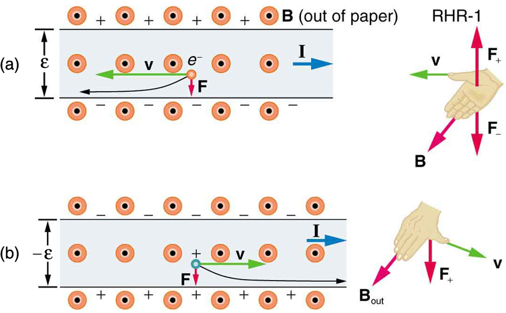
One very important use of the Hall effect is to determine whether positive or negative charges carries the current. Note that in [link] (b), where positive charges carry the current, the Hall emf has the sign opposite to when negative charges carry the current. Historically, the Hall effect was used to show that electrons carry current in metals and it also shows that positive charges carry current in some semiconductors. The Hall effect is used today as a research tool to probe the movement of charges, their drift velocities and densities, and so on, in materials. In 1980, it was discovered that the Hall effect is quantized, an example of quantum behavior in a macroscopic object.
The Hall effect has other uses that range from the determination of blood flow rate to precision measurement of magnetic field strength. To examine these quantitatively, we need an expression for the Hall emf, , across a conductor. Consider the balance of forces on a moving charge in a situation where , , and are mutually perpendicular, such as shown in [link] . Although the magnetic force moves negative charges to one side, they cannot build up without limit. The electric field caused by their separation opposes the magnetic force, , and the electric force, , eventually grows to equal it. That is,
Notification Switch
Would you like to follow the 'College physics for ap® courses' conversation and receive update notifications?

|
|

|
|

|
|

|
|

|
|

|
|

|
|

|
|

|
|
|
|
|

|