<< Chapter < Page Chapter >> Page >
First of four images shows an incident ray 1 coming from an object (a girl ) placed on the axis. After refraction, the ray passes through F on other side of the lens. Second of four images shows an incident ray 2 passing through the center without any deviation. Third of four images shows an incident ray passing through F, which after refraction goes parallel to the axis. Fourth image shows a combination of all three rays, 1, 2, and 3, incident on a convex lens; after refraction, they converge or cross at a point below the axis at some distance from F. Here the height of the object h sub o is the height of the girl above the axis and h sub i is the height of the image below the axis. The distance from the center to point F is small f. The distance from the center to the girl is d sub o and that to the image is d sub i.
Ray tracing is used to locate the image formed by a lens. Rays originating from the same point on the object are traced—the three chosen rays each follow one of the rules for ray tracing, so that their paths are easy to determine. The image is located at the point where the rays cross. In this case, a real image—one that can be projected on a screen—is formed.

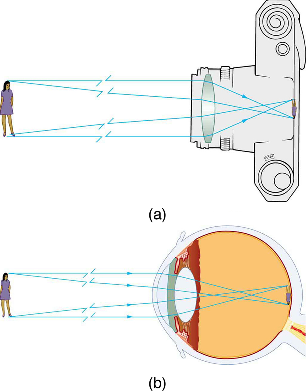
The image formed in [link] is a real image    , meaning that it can be projected. That is, light rays from one point on the object actually cross at the location of the image and can be projected onto a screen, a piece of film, or the retina of an eye, for example. [link] shows how such an image would be projected onto film by a camera lens. This figure also shows how a real image is projected onto the retina by the lens of an eye. Note that the image is there whether it is projected onto a screen or not.

Real image

The image in which light rays from one point on the object actually cross at the location of the image and can be projected onto a screen, a piece of film, or the retina of an eye is called a real image.

Figure (a) shows incident rays coming from an object (a girl) and falling on a convex lens in a camera. The rays after refraction produce an inverted, real, and diminished image on the film of the camera. Figure (b) shows the same object in front of a human eye. The rays from the object fall on the convex lens and on refraction produce a real, inverted, and diminished image on the retina of the eyeball.
Real images can be projected. (a) A real image of the person is projected onto film. (b) The converging nature of the multiple surfaces that make up the eye result in the projection of a real image on the retina.

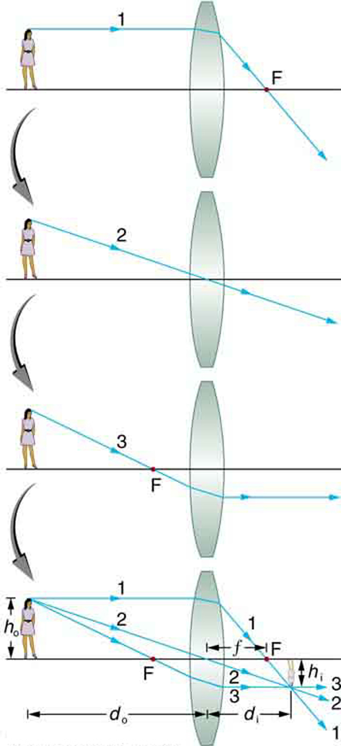
Several important distances appear in [link] . We define d o to be the object distance, the distance of an object from the center of a lens. Image distance d i is defined to be the distance of the image from the center of a lens. The height of the object and height of the image are given the symbols h o and h i , respectively. Images that appear upright relative to the object have heights that are positive and those that are inverted have negative heights. Using the rules of ray tracing and making a scale drawing with paper and pencil, like that in [link] , we can accurately describe the location and size of an image. But the real benefit of ray tracing is in visualizing how images are formed in a variety of situations. To obtain numerical information, we use a pair of equations that can be derived from a geometric analysis of ray tracing for thin lenses. The thin lens equations are

1 d o + 1 d i = 1 f

and

h i h o = d i d o = m.

We define the ratio of image height to object height ( h i / h o size 12{h rSub { size 8{i} } /h rSub { size 8{o} } } {} ) to be the magnification     m size 12{m} {} . (The minus sign in the equation above will be discussed shortly.) The thin lens equations are broadly applicable to all situations involving thin lenses (and “thin” mirrors, as we will see later). We will explore many features of image formation in the following worked examples.

Image distance

The distance of the image from the center of the lens is called image distance.

Thin lens equations and magnification

1 d o + 1 d i = 1 f
h i h o = d i d o = m

Finding the image of a light bulb filament by ray tracing and by the thin lens equations

A clear glass light bulb is placed 0.750 m from a convex lens having a 0.500 m focal length, as shown in [link] . Use ray tracing to get an approximate location for the image. Then use the thin lens equations to calculate (a) the location of the image and (b) its magnification. Verify that ray tracing and the thin lens equations produce consistent results.

Questions & Answers

what is biology
Hajah Reply
the study of living organisms and their interactions with one another and their environments
AI-Robot
what is biology
Victoria Reply
HOW CAN MAN ORGAN FUNCTION
Alfred Reply
the diagram of the digestive system
Assiatu Reply
allimentary cannel
Ogenrwot
How does twins formed
William Reply
They formed in two ways first when one sperm and one egg are splited by mitosis or two sperm and two eggs join together
Oluwatobi
what is genetics
Josephine Reply
Genetics is the study of heredity
Misack
how does twins formed?
Misack
What is manual
Hassan Reply
discuss biological phenomenon and provide pieces of evidence to show that it was responsible for the formation of eukaryotic organelles
Joseph Reply
what is biology
Yousuf Reply
the study of living organisms and their interactions with one another and their environment.
Wine
discuss the biological phenomenon and provide pieces of evidence to show that it was responsible for the formation of eukaryotic organelles in an essay form
Joseph Reply
what is the blood cells
Shaker Reply
list any five characteristics of the blood cells
Shaker
lack electricity and its more savely than electronic microscope because its naturally by using of light
Abdullahi Reply
advantage of electronic microscope is easily and clearly while disadvantage is dangerous because its electronic. advantage of light microscope is savely and naturally by sun while disadvantage is not easily,means its not sharp and not clear
Abdullahi
cell theory state that every organisms composed of one or more cell,cell is the basic unit of life
Abdullahi
is like gone fail us
DENG
cells is the basic structure and functions of all living things
Ramadan
What is classification
ISCONT Reply
is organisms that are similar into groups called tara
Yamosa
in what situation (s) would be the use of a scanning electron microscope be ideal and why?
Kenna Reply
A scanning electron microscope (SEM) is ideal for situations requiring high-resolution imaging of surfaces. It is commonly used in materials science, biology, and geology to examine the topography and composition of samples at a nanoscale level. SEM is particularly useful for studying fine details,
Hilary
cell is the building block of life.
Condoleezza Reply
Got questions? Join the online conversation and get instant answers!
Jobilize.com Reply
Practice Key Terms 8

Get Jobilize Job Search Mobile App in your pocket Now!

Get it on Google Play Download on the App Store Now


Source:  OpenStax, College physics for ap® courses. OpenStax CNX. Nov 04, 2016 Download for free at https://legacy.cnx.org/content/col11844/1.14
Google Play and the Google Play logo are trademarks of Google Inc.

Notification Switch

Would you like to follow the 'College physics for ap® courses' conversation and receive update notifications?

Ask