By applying Kirchhoff’s rules, we generate equations that allow us to find the unknowns in circuits. The unknowns may be currents, emfs, or resistances. Each time a rule is applied, an equation is produced. If there are as many independent equations as unknowns, then the problem can be solved. There are two decisions you must make when applying Kirchhoff’s rules. These decisions determine the signs of various quantities in the equations you obtain from applying the rules.
When applying Kirchhoff’s first rule, the junction rule, you must label the current in each branch and decide in what direction it is going. For example, in
[link] ,
[link] , and
[link] , currents are labeled
,
,
, and
, and arrows indicate their directions. There is no risk here, for if you choose the wrong direction, the current will be of the correct magnitude but negative.
When applying Kirchhoff’s second rule, the loop rule, you must identify a closed loop and decide in which direction to go around it, clockwise or counterclockwise. For example, in
[link] the loop was traversed in the same direction as the current (clockwise). Again, there is no risk; going around the circuit in the opposite direction reverses the sign of every term in the equation, which is like multiplying both sides of the equation by
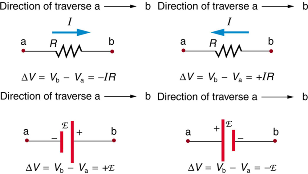
[link] and the following points will help you get the plus or minus signs right when applying the loop rule. Note that the resistors and emfs are traversed by going from a to b. In many circuits, it will be necessary to construct more than one loop. In traversing each loop, one needs to be consistent for the sign of the change in potential. (See
[link] .)
Each of these resistors and voltage sources is traversed from a to b. The potential changes are shown beneath each element and are explained in the text. (Note that the script E stands for emf.)
When a resistor is traversed in the same direction as the current, the change in potential is
. (See
[link] .)
When a resistor is traversed in the direction opposite to the current, the change in potential is
. (See
[link] .)
When an emf is traversed from
to + (the same direction it moves positive charge), the change in potential is +emf. (See
[link] .)
When an emf is traversed from + to
(opposite to the direction it moves positive charge), the change in potential is
emf. (See
[link] .)
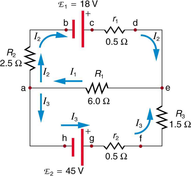
Calculating current: using kirchhoff’s rules
Find the currents flowing in the circuit in
[link] .
This circuit is similar to that in
[link] , but the resistances and emfs are specified. (Each emf is denoted by script E.) The currents in each branch are labeled and assumed to move in the directions shown. This example uses Kirchhoff’s rules to find the currents.
Strategy
This circuit is sufficiently complex that the currents cannot be found using Ohm’s law and the series-parallel techniques—it is necessary to use Kirchhoff’s rules. Currents have been labeled
,
, and
in the figure and assumptions have been made about their directions. Locations on the diagram have been labeled with letters a through h. In the solution we will apply the junction and loop rules, seeking three independent equations to allow us to solve for the three unknown currents.
the study of living organisms and their interactions with one another and their environment.
Wine
discuss the biological phenomenon and provide pieces of evidence to show that it was responsible for the formation of eukaryotic organelles in an essay form
advantage of electronic microscope is easily and clearly while disadvantage is dangerous because its electronic. advantage of light microscope is savely and naturally by sun while disadvantage is not easily,means its not sharp and not clear
Abdullahi
cell theory state that every organisms composed of one or more cell,cell is the basic unit of life
Abdullahi
is like gone fail us
DENG
cells is the basic structure and functions of all living things
A scanning electron microscope (SEM) is ideal for situations requiring high-resolution imaging of surfaces. It is commonly used in materials science, biology, and geology to examine the topography and composition of samples at a nanoscale level. SEM is particularly useful for studying fine details,