

| << Chapter < Page | Chapter >> Page > |
Extensive testing was done to determine the effectiveness of our communication system. Since the communication is done auditorily, both laptops must be within close range. One laptop transmits via a speaker, and the other records the sound. To test how effective our communication was, we calculated the number of bit errors that occurred from transmission to reception. Various 500 bit sequences were sent; then, the received, decoded message was XORed with the original bit sequence to determine how many bit errors occurred.
Initially, when first testing our system, our bit error was consistently around 250 out of 500 bits. This led us to believe that our demodulator was simply guessing when decoding, but upon further investigation, our bit error occurred in blocks as in the graph below.
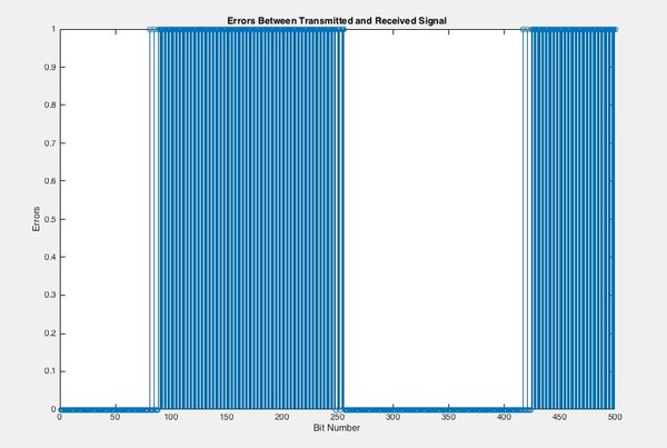
The message would be decoded correctly at first, but suddenly, over 100 bits would be consistently decoded incorrectly before the modulator would correct itself. To see what was underlying this problem, we compared the received analog waveform with the transmitted waveform.
This revealed one major problem: there existed a frequency mismatch between the transmitted and received signal. Both signals originally began in phase, but due to the frequency mismatch, would become out of phase enough to confuse the BPSK demodulator. The graph below shows the same bit of the sent and received signal, represented as an analog waveform. This graph shows the frequency mismatch between the two signals.
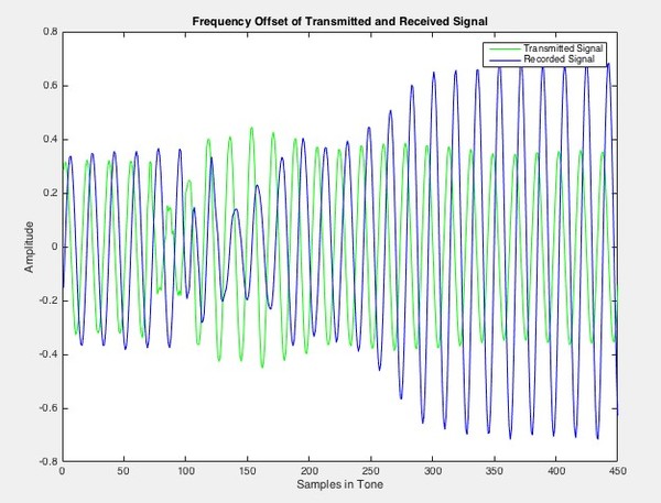
At points, the received signal looks around 180 degrees out of phase with the original transmitted signal. This explains the blocks of bit error and why the demodulator would consistently decode an entire block of bits incorrectly. However, when the two signals became 360 degrees out of phase, the demodulator would again begin to decode correctly.
To confirm the frequency mismatch, we played and recorded a pure sine wave at our carrier frequency: 2250 Hz. The sine wave would be played from one laptop and recorded on both laptops. Despite the fact that the same sampling rate was picked for recording, the DFT’s of both recorded signals revealed the frequency mismatch. The frequency of the recorded sine wave on the laptop that did not play the sine wave had a spike at 2250.22 Hz. This slight frequency shift gave rise to the blocks of error.
We mitigated this effect by transmitting the signal from the first laptop, recording on the second laptop, and then replaying the recorded signal back to the first laptop. Although the stored message on the second computer would be corrupted, the original laptop decoded the replayed signal with zero bit error, meeting the goal of our project.
Notification Switch
Would you like to follow the 'Elec 301 projects fall 2015' conversation and receive update notifications?

|
|

|
|

|
|

|
|

|
|
|
|
|
|
|
|
|
|
|
|
|
|

|