

| << Chapter < Page | Chapter >> Page > |
SSPD_Chapter 7_Part 6_Basic Circuit Concepts_continued 3
7.6.4. Formal Estimation of CMOS Inverter delay.
In Figure 7.6.4.1 we show a CMOS Inverter being driven by square wave and loaded with input capacitance of the subsequent stage. We model the CMOS Inverter during switching transients by constant current source driving the load capacitance.
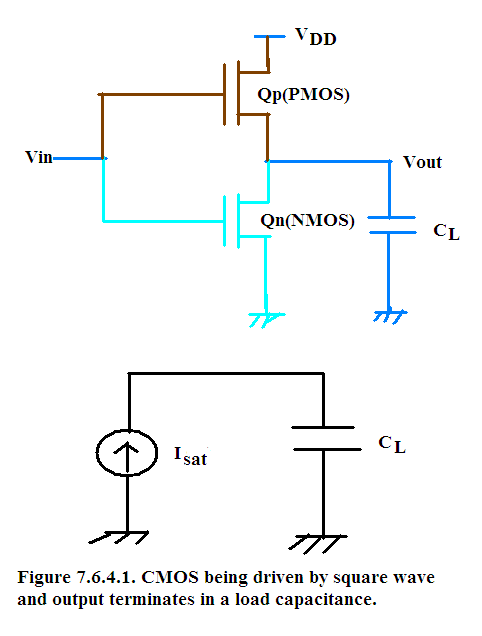
The switching transient is shown in Figure 7.6.4.2.
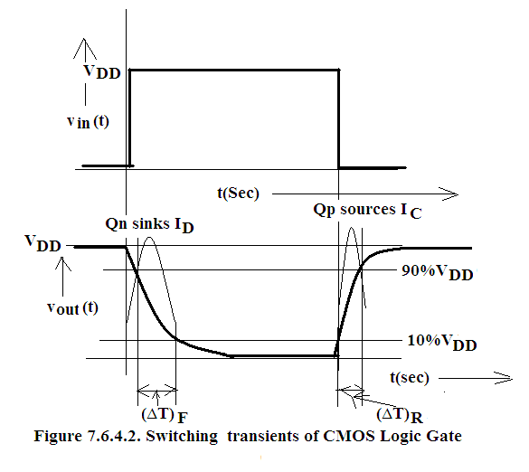
As can be seen in Figure 7.6.4.2, during HIGH to LOW switching NMOS (Q n ) provides the low impedance path to ground and hence sinks the discharge current. Hence saturation current of NMOS provides the I D .
Similarly during LOW to HIGH switching PMOS (Q p ) provides the low impedance path from V DD bus to the load capacitance and hence sources the charging current. Hence saturation current of PMOS provides the I C .
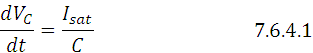
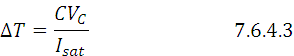
Referring to the circuit model in Figure 7.6.4.1 we see that:
Rate of change of capacitance voltage = Constant Current/C
Therefore:
Therefore:
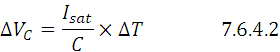
Therefore:
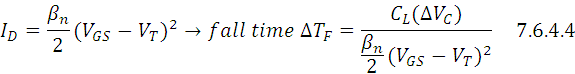
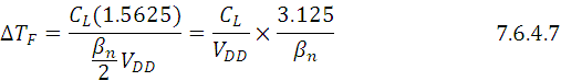
During output HIGH to LOW transient: NMOS (Q n ) is sinking the current from the load capacitance hence constant current source is a discharge current I D coming as the saturation current of NMOS where
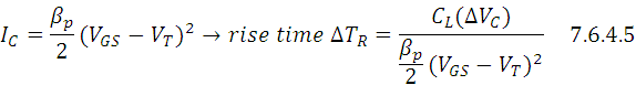
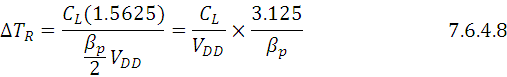
During output LOW to HIGH transient:PMOS(Q p ) is sourcing the current to the load capacitance hence constant current source is a charging current I C coming as the saturation current of PMOS where
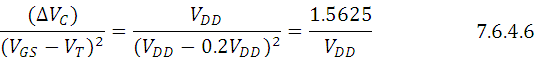
But ∆V C = V DD , V GS = V DD and V T = 0.2 V DD therefore
Substituting Eq.7.6.4.6 in Eq 7.6.4.4 and Eq.7.6.4.5 we get:
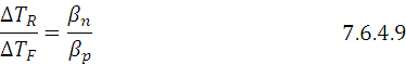
Dividing Eq 7.6.4.8 by Eq.7.6.4.7 we get:
From Basic Electrical Properties we know that
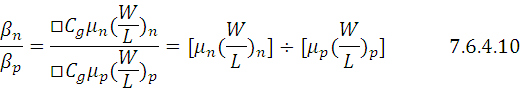
From Device Physics we know that
We also know from section 7.3.12 titled ‘optimization of geometric parameters to achieve the beswt CMOS performance’ that :
Substituting the two conditions stated by Eq.7.6.4.8 and Eq.7.6.4.9 in Eq 7.6.4.7 we get
Eq 7.6.4.10 implies that we will get symmetric switching transients as well as maximum Noise Margin if satisfy the condition stated in Eq 7.6.4.11 namely
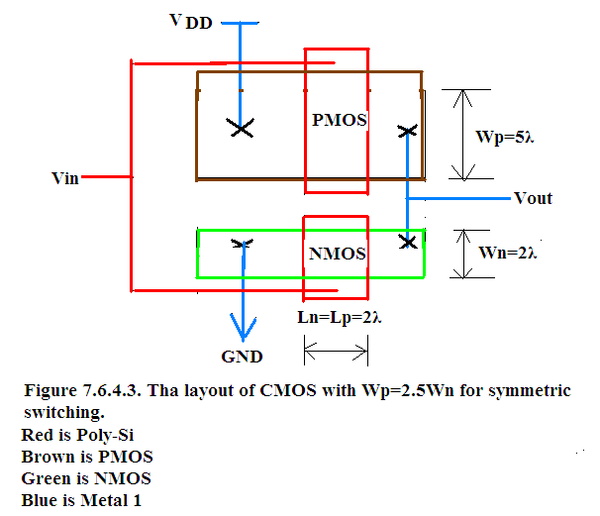
Hence CMOS layout will be as shown in Figure 7.6.4.3 for optimum performance in all sense of the word i.e in the sense of switching transient and in the sense of noise margin.
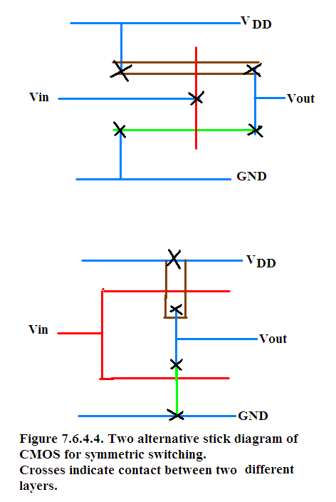
Two alternative layouts are shown in Figure 7.6.4.4.
In all the three figures, where metal has to connect to Poly-Si or to n-channel or to p-channel there a contact has to be made symbolized by black cross.
Notification Switch
Would you like to follow the 'Solid state physics and devices-the harbinger of third wave of civilization' conversation and receive update notifications?

|
|

|
|
|
|

|
|

|
|

|
|
|
|
|
|
|

|
|

|