

| << Chapter < Page | Chapter >> Page > |
DSD_Chapter 6_Part 1_Digital Instruments+Clocks+Scoreboards
In the Introduction of Chapter 6, we designed BCD-to Seven Segment decoder-driver. We will use it in Digital Instruments, Clocks and Scoreboards to display decimal numbers which may indicate number of items or hour-minutes-seconds or number of runs scored.
Digital Instruments, Clocks and Scoreboards use the basic sub-system of 7-Segment display for displaying the decimal value of the binary code obtained from a counter. The counter may be counting some items under processing or it may be counting hour-minutes-seconds or it may be counting the runs as the case may be. A system displaying the overall count is a Finite State Sysem and its state diagram has to be drawn.
Here we will take up the design of a Cricket-Scoreboard as shown in Figure 1.
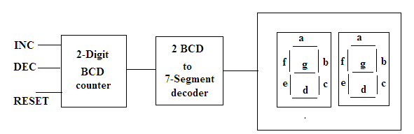
Figure 1. The Block Diagram of the Cricket-Scoreboard.
6.1.1. Data Path.
The scoreboard has three inputs: INC, DEC and RESET.
When RESET is TRUE the scoreboard is resetted to “00”. To prevent accidental erasure, RESET must be pressed for five consecutive cycles. Hence there will be a 3-bit reset counter known as rstcnt .
When INC is TRUE the score is incremented. When DEC is TRUE the score is decremented. When INC and DEC, both, are true then no change occurs.
There will be two-digit BCD counter which can count from decimal 00 to decimal 99. To display the two-digit decimal number we wil have two 7-segment displays.
There will be two ‘BCD to 7-segment decoder driver’ which will drive the two ‘7-segment displays’.
6.1.2. Controller.
The scoreboard will have a INITIALIZATION STATE and a COUNT STATE. Hence there are two well defined States namely S0(Clear State) and S1(Count State). How the state transitions take place are shown in Figure 2 , state diagram, and in Table 1, state table.

Figure 2. State Diagram of Cricket Scoreboard displaying the number of runs scored.
Table 1. State Table of the scoreboard.
| Initial state S0(initialization state) | Count State S1(count state)For every clock cycle incrementing or decrementing is done. |
| BCD counter is resetted or cleared.RESET<= 0; | If rst arrives, rstcnt is incremented. If rstcnt has reached 4 and rst =1 is persisting this means RESET has to done hence system reverts to S0 |
| If inc = 1 and dec = 0, counter is incremented. Add1 indicates that a increment has taken place. | |
| If inc = 0 and dec = 1, counter is decremented. Sub1 indicates that a decrement has taken place. | |
| If rst = 0 then rstcnt is reset. | |
| If { inc=1 and dec=1} or {inc=0 and dec=0} then rstcnt is resetted and no change in the counter |
6.1.3. VHDL MODEL
7-Segment Displays are declared as unsigned 7-bit vectors namely seg7disp0 and seg7disp1 .
The unsigned vector is used so that overload ‘+’ operator is used for incrementing the counter by 1 and ‘-‘ operator is used for decrementing the counter by 1.
The BCD-to-7 Segment decoder driver can be implemented by the following look-up table :
Table 2.
Notification Switch
Would you like to follow the 'Digital system design using vhdl' conversation and receive update notifications?

|
|

|
|

|
|

|
|

|
|

|
|

|
|

|
|

|
|
|
|