

| << Chapter < Page | Chapter >> Page > |
The fetch, indirect, and interrupt cycles are simple and predictable. Each involves a small, fixed sequence of micro-operations and, in each ease, the same micro-operations are repealed each time around. This is not true of the execute cycle. For a machine with N different opcodes, there are N different sequences of micro-operations that can occur. Let us consider several hypothetical examples.
First, consider an add instruction:
ADD R1, X
which adds the contents of the location X to register Rl. The following sequence of micro-operations might occur:
t1: MAR<= (IR(address))
t2: MBR<= Memory
t3: Rl<= (Rl) + (MBR)
We begin with the IR containing the ADD instruction. In the first step, the address portion of the IR is loaded into the MAR. Then the referenced memory location is read. Finally, the contents of R1 and MBR are added by the ALU. Again, this is a simplified example. Additional micro-operations may be required to extract the register reference from the IR and perhaps to stage the ALU inputs or outputs in some intermediate registers.Let us look at two more complex examples. A common instruction is increment and skip if zero:
ISZ X
The content of location X is incremented by 1. If the result is 0, the next instruction is skipped. A possible sequence of micro-operations is
t1: MAR<= (CR(address) )
t2: MBR<= Memory
t3: MBR<= (MBR) - 1
t4: Memory<= (MBR)
If ((MBR) = 0) then (PC<= (PC) + I)
The new feature introduced here is the conditional action. The PC is incremented if (MBR) = 0; this test and action can be implemented as one micro-operation. Note also that this micro-operation can be performed during the same time unit during which the updated value in MBR is stored back to memory.
Finally, consider a subroutine call instruction. As an example, consider a branch-and-save-address instruction:
BSA X
The address of the instruction that follows the BSA instruction is saved in location X, and execution continues al location X - l. The saved address will later be used for return. This is a straightforward technique for providing subroutine calls. the following micro-operations suffice:
t1 : MAR<= (IR(address))
MBR<= (PC)
t2: PC<= (IR(address)) Memory<= (MBR)
t3: PC<= (PC) + I
The address in the PC at the start of the instruction is the address of the next instruction in sequence. This is saved at the address designated in Ihe IK. The latter address is also incremented to provide the address of the instruction for the next instruction cycle.
We have seen that each phase of the instruction cycle can be decomposed into a sequence of elementary micro-operations. In our example, there is one sequence each for the fetch, indirect, and interrupt cycles, and, for the execute cycle, there is one sequence of micro-operations for each opcode. To complete the picture, we need to tie sequences of micro-operations together, and this is done in Figure 6.3.
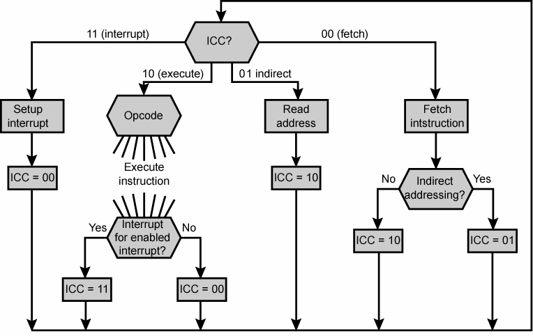
Figure 6.3 Flowchart for Instruction Cycle
We assume a new 2-bit register called the instruction cycle code (ICC). The ICC designates the state of the processor in terms of which portion of the cycle it is in:
Notification Switch
Would you like to follow the 'Computer architecture' conversation and receive update notifications?

|
|

|
|

|
|

|
|

|
|

|
|

|
|
|
|
|

|
|

|