

| << Chapter < Page | Chapter >> Page > |
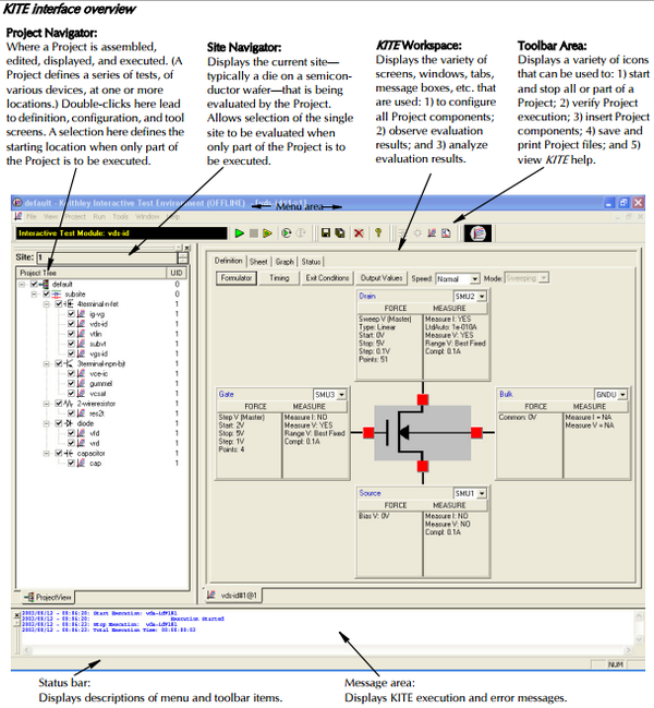
| Connection | Description |
|---|---|
| SMU1 | Medium power source with low noise preamplifier |
| SMU2 | Medium power source without preamplifier |
| SMU3 | High Power |
| GNRD | For large currents |
Voltage sweeps are a great way to learn about the device. [link] shows a typical plot of drain-source voltage sweeps at various gate-source voltages while measuring the drain current, I D for a n-channel JFET. The V-I characteristics have four distinct regions. Analysis of these regions can provides critical information about the device characteristics such as the pinch off voltage, V P , transcunductance gain, g m , drain-source channel resistance, R DS , and power dissipation, P D .
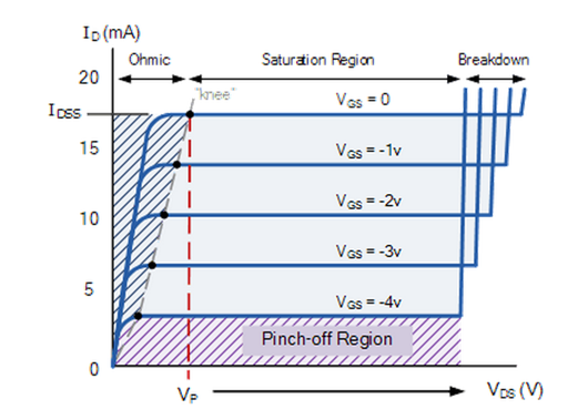
This region is bounded by V DS <V P . Here the JFET begins to flow a drain current with a linear response to the voltage, behaving like a variable resistor. In this region the drain-source channel resistance, R DS is modeled by [link] , where ΔV DS is the change in drain-source voltage, ΔI D is the change in drain current, and g m is the transcunductance gain. Solving for g m results in [link] .
This is the region where the JFET is completely “ON”. The maximum amount of current is flowing for the given gate-source voltage. In this region the drain current can be modeled by the [link] , where I D is the drain current, I DSS is the maximum current, V GS is the gate-source voltage, and V P is the pinch off voltage. Solving for the pinch off voltage results in [link] .
This region is characterized by the sudden increase in current. The drain-source voltage supplied exceeds the resistive limit of the semiconducting channel, resulting in the transistor to break down and flow an uncontrolled current.
In this region the gate-source voltage is sufficient to restrict the flow through the channel, in effect cutting off the drain current. The power dissipation, P D , can be solved utilizing Ohms law (I = V/R) for any region using [link] .
The p-channel JFET V-I characteristics behave similarly except that the voltages are reversed. Specifically, the pinch off point is reached when the gate-source voltage is increased in a positive direction, and the saturation region is met when the drain-source voltage is increased in the negative direction.
[link] shows a typical plot of drain-source voltage sweeps at various gate-source voltages while measuring the drain current, I D for an ideal n-channel enhancement MOSFET. Like JFETs, the V-I characteristics of MOSFETS have distinct regions that provide valuable information about device transport properties.
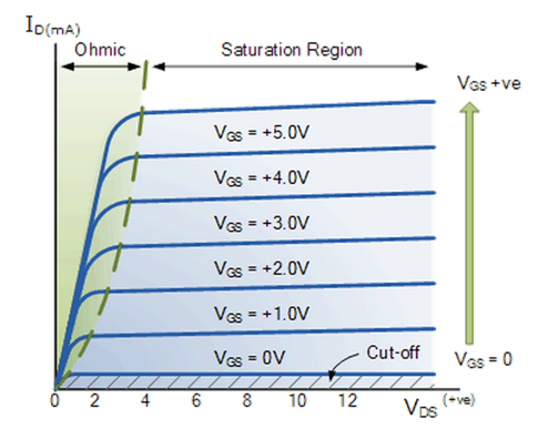
The n-channel enhanced MOSFET behaves linearly, acting like a variable resistor, when the gate-source voltage is greater than the threshold voltage and the drain-source voltage is greater than the gate-source voltage. In this region the drain current can be modeled by [link] , where I D is the drain current, V GS is the gate-source voltage, V T is the threshold voltage, V DS is the drain-source voltage, and k is the geometric factor described by [link] , where µ n is the charge-carrier effective mobility, C OX is the gate oxide capacitance, W is the channel width, and L is the channel length.
In this region the MOSFET is considered fully “ON”. The drain current for the saturation region is modeled by [link] . The drain current is mainly influenced by the gate-source voltage, while the drain-source voltage has no effect.
Solving for the threshold voltage V T results in [link] .
When the gate-source voltage, V GS , is below the threshold voltage V T the charge carriers in the channel are not available “cutting off” the charge flow. Power dissipation for MOSFETs can also be solved using equation 6 in any region as in the JFET case.
The typical I-V characteristics for the whole family of FETs seen in [link] are plotted in [link] .
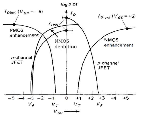
From [link] we can see how the doping schemes that lead to enhancement and depletion are displaced along the V GS axis. In addition, from the plot the ON or OFF state can be determined for a given gate-source voltage, where (+) is positive, (0) is zero, and (-) is negative, as seen in [link] .
| FET Type | V GS = (-) | V GS = 0 | V GS = (+) |
|---|---|---|---|
| n-channel JFET | OFF | ON | ON |
| p-channel JFET | ON | ON | OFF |
| n-channel depletion MOSFET | OFF | ON | ON |
| p-channel depletion MOSFET | ON | ON | OFF |
| n-channel enhancement MOSFET | OFF | OFF | ON |
| p-channel enhancement MOSFET | ON | ON | OFF |
Notification Switch
Would you like to follow the 'Physical methods in chemistry and nano science' conversation and receive update notifications?

|
|
|
|

|
|

|
|

|
|
|
|
|

|
|
|
|
|

|
|
|