

| << Chapter < Page | Chapter >> Page > |
Semiconductors have many applications in modern electronics. We describe some basic semiconductor devices in this section. A great advantage of using semiconductors for circuit elements is the fact that many thousands or millions of semiconductor devices can be combined on the same tiny piece of silicon and connected by conducting paths. The resulting structure is called an integrated circuit (ic), and ic chips are the basis of many modern devices, from computers and smartphones to the internet and global communications networks.
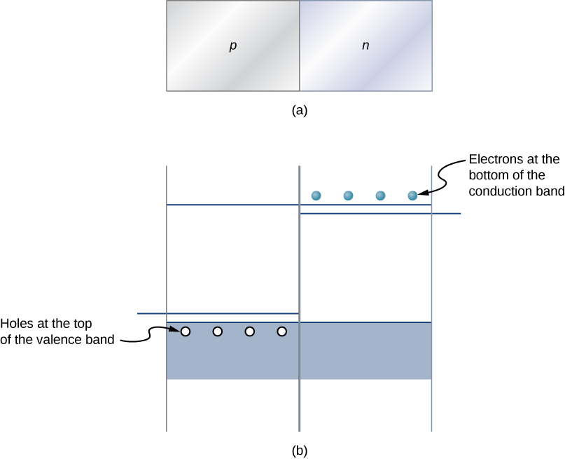
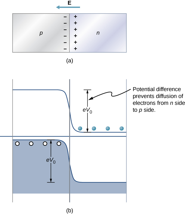
Perhaps the simplest device that can be created with a semiconductor is a diode. A diode is a circuit element that allows electric current to flow in only one direction, like a one-way valve (see Model of Conduction in Metals ). A diode is created by joining a p -type semiconductor to an n -type semiconductor ( [link] ). The junction between these materials is called a p-n junction . A comparison of the energy bands of a silicon-based diode is shown in [link] (b). The positions of the valence and conduction bands are the same, but the impurity levels are quite different. When a p-n junction is formed, electrons from the conduction band of the n -type material diffuse to the p -side, where they combine with holes in the valence band. This migration of charge leaves positive ionized donor ions on the n -side and negative ionized acceptor ions on the p -side, producing a narrow double layer of charge at the p - n junction called the depletion layer . The electric field associated with the depletion layer prevents further diffusion. The potential energy for electrons across the p-n junction is given by [link] .
The behavior of a semiconductor diode can now be understood. If the positive side of the battery is connected to the n -type material, the depletion layer is widened, and the potential energy difference across the p-n junction is increased. Few or none of the electrons (holes) have enough energy to climb the potential barrier, and current is significantly reduced. This is called the reverse bias configuration . On the other hand, if the positive side of a battery is connected to the p -type material, the depletion layer is narrowed, the potential energy difference across the p-n junction is reduced, and electrons (holes) flow easily. This is called the forward bias configuration of the diode. In sum, the diode allows current to flow freely in one direction but prevents current flow in the opposite direction. In this sense, the semiconductor diode is a one-way valve.
Notification Switch
Would you like to follow the 'University physics volume 3' conversation and receive update notifications?

|
|

|
|

|
|

|
|

|
|
|
|
|

|
|

|
|

|
|

|