

| << Chapter < Page | Chapter >> Page > |
To obtain an expression for the magnification that involves only the lens parameters, note that the focal plane of the objective lens lies very close to the focal plan of the eyepiece. If we assume that these planes are superposed, we have the situation shown in [link] .
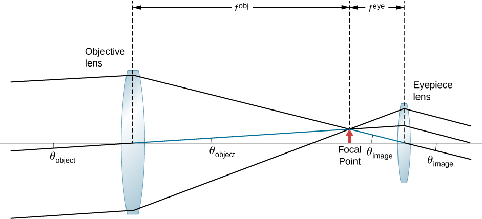
We further assume that the angles and are small, so that the small-angle approximation holds ( ). If the image formed at the focal plane has height h , then
where the minus sign is introduced because the height is negative if we measure both angles in the counterclockwise direction. Inserting these expressions into [link] gives
Thus, to obtain the greatest angular magnification, it is best to have an objective with a long focal length and an eyepiece with a short focal length. The greater the angular magnification M , the larger an object will appear when viewed through a telescope, making more details visible. Limits to observable details are imposed by many factors, including lens quality and atmospheric disturbance. Typical eyepieces have focal lengths of 2.5 cm or 1.25 cm. If the objective of the telescope has a focal length of 1 meter, then these eyepieces result in magnifications of and , respectively. Thus, the angular magnifications make the image appear 40 times or 80 times closer than the real object.
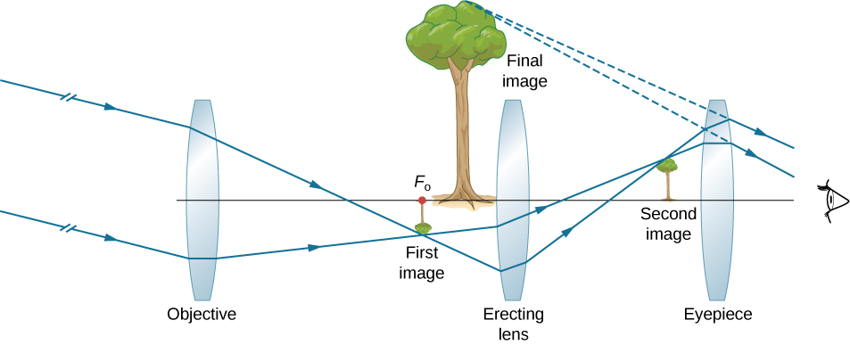
The minus sign in the magnification indicates the image is inverted, which is unimportant for observing the stars but is a real problem for other applications, such as telescopes on ships or telescopic gun sights. If an upright image is needed, Galileo’s arrangement in part (a) of [link] can be used. But a more common arrangement is to use a third convex lens as an eyepiece, increasing the distance between the first two and inverting the image once again, as seen in [link] .
The largest refracting telescope in the world is the 40-inch diameter Yerkes telescope located at Lake Geneva, Wisconsin ( [link] ), and operated by the University of Chicago.
It is very difficult and expensive to build large refracting telescopes. You need large defect-free lenses, which in itself is a technically demanding task. A refracting telescope basically looks like a tube with a support structure to rotate it in different directions. A refracting telescope suffers from several problems. The aberration of lenses causes the image to be blurred. Also, as the lenses become thicker for larger lenses, more light is absorbed, making faint stars more difficult to observe. Large lenses are also very heavy and deform under their own weight. Some of these problems with refracting telescopes are addressed by avoiding refraction for collecting light and instead using a curved mirror in its place, as devised by Isaac Newton. These telescopes are called reflecting telescopes.
Notification Switch
Would you like to follow the 'University physics volume 3' conversation and receive update notifications?

|
|
|
|
|
|
|
|
|
|
|

|
|

|
|

|
|

|
|
|
|
|

|