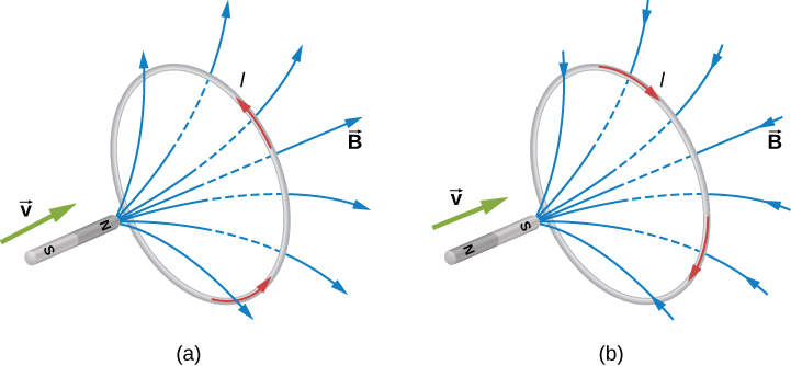
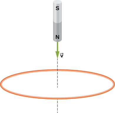
The change in magnetic flux caused by the approaching magnet induces a current in the loop. (a) An approaching north pole induces a counterclockwise current with respect to the bar magnet. (b) An approaching south pole induces a clockwise current with respect to the bar magnet.
Part (b) of the figure shows the south pole of a magnet moving toward a conducting loop. In this case, the flux through the loop due to the field of the magnet increases because the number of field lines directed from the back to the front of the loop is increasing. To oppose this change, a current is induced in the loop whose field lines through the loop are directed from the front to the back. Equivalently, we can say that the current flows in a direction so that the face of the loop nearer the approaching magnet is a south pole, which then repels the approaching south pole of the magnet. By RHR-2, your thumb points away from the bar magnet. Your fingers wrap in a clockwise fashion, which is the direction of the induced current.
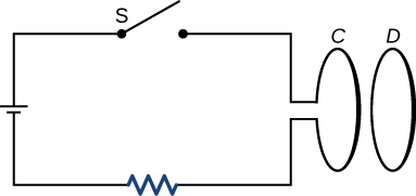
Another example illustrating the use of Lenz’s law is shown in
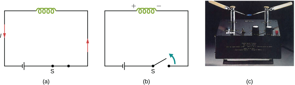
[link] . When the switch is opened, the decrease in current through the
solenoid causes a decrease in magnetic flux through its coils, which induces an emf in the solenoid. This emf must oppose the change (the termination of the current) causing it. Consequently, the induced emf has the polarity shown and drives in the direction of the original current. This may generate an arc across the terminals of the switch as it is opened.
(a) A solenoid connected to a source of emf. (b) Opening switch S terminates the current, which in turn induces an emf in the solenoid. (c) A potential difference between the ends of the sharply pointed rods is produced by inducing an emf in a coil. This potential difference is large enough to produce an arc between the sharp points.
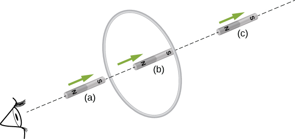
Check Your Understanding Find the direction of the induced current in the wire loop shown below as the magnet enters, passes through, and leaves the loop.
To the observer shown, the current flows clockwise as the magnet approaches, decreases to zero when the magnet is centered in the plane of the coil, and then flows counterclockwise as the magnet leaves the coil.
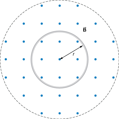
A magnetic field
is directed outward perpendicular to the plane of a circular coil of radius
(
[link] ). The field is cylindrically symmetrical with respect to the center of the coil, and its magnitude decays exponentially according to
where
B is in teslas and
t is in seconds. (a) Calculate the emf induced in the coil at the times
and
(b) Determine the current in the coil at these three times if its resistance is
A circular coil in a decreasing magnetic field.
Strategy
Since the magnetic field is perpendicular to the plane of the coil and constant over each spot in the coil, the dot product of the magnetic field
and normal to the area unit vector
turns into a multiplication. The magnetic field can be pulled out of the integration, leaving the flux as the product of the magnetic field times area. We need to take the time derivative of the exponential function to calculate the emf using Faraday’s law. Then we use Ohm’s law to calculate the current.
Solution
Since
is perpendicular to the plane of the coil, the magnetic flux is given by
From Faraday’s law, the magnitude of the induced emf is
Since
is directed out of the page and is decreasing, the induced current must flow counterclockwise when viewed from above so that the magnetic field it produces through the coil also points out of the page. For all three times, the sense of ε is counterclockwise; its magnitudes are
From Ohm’s law, the respective currents are
and
Significance
An emf voltage is created by a changing magnetic flux over time. If we know how the magnetic field varies with time over a constant area, we can take its time derivative to calculate the induced emf.
The current through the windings of a solenoid with
turns per meter is changing at a rate
(See
Sources of Magnetic Fields for a discussion of solenoids.) The solenoid is 50-cm long and has a cross-sectional diameter of 3.0 cm. A small coil consisting of
closely wound turns wrapped in a circle of diameter 1.0 cm is placed in the middle of the solenoid such that the plane of the coil is perpendicular to the central axis of the solenoid. Assuming that the infinite-solenoid approximation is valid at the location of the small coil, determine the magnitude of the emf induced in the coil.
Strategy
The magnetic field in the middle of the solenoid is a uniform value of
This field is producing a maximum magnetic flux through the coil as it is directed along the length of the solenoid. Therefore, the magnetic flux through the coil is the product of the solenoid’s magnetic field times the area of the coil. Faraday’s law involves a time derivative of the magnetic flux. The only quantity varying in time is the current, the rest can be pulled out of the time derivative. Lastly, we include the number of turns in the coil to determine the induced emf in the coil.
Solution
Since the field of the solenoid is given by
the flux through each turn of the small coil is
where
d is the diameter of the coil. Now from Faraday’s law, the magnitude of the emf induced in the coil is
Significance
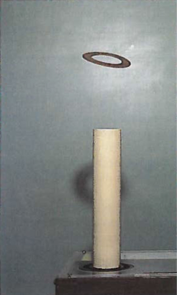
When the current is turned on in a vertical solenoid, as shown in
[link] , the ring has an induced emf from the solenoid’s changing magnetic flux that opposes the change. The result is that the ring is fired vertically into the air.
The jumping ring. When a current is turned on in the vertical solenoid, a current is induced in the metal ring. The stray field produced by the solenoid causes the ring to jump off the solenoid.
Visit this
website for a demonstration of the jumping ring from MIT.
Summary
We can use Lenz’s law to determine the directions of induced magnetic fields, currents, and emfs.
The direction of an induced emf always opposes the change in magnetic flux that causes the emf, a result known as Lenz’s law.
Conceptual questions
The circular conducting loops shown in the accompanying figure are parallel, perpendicular to the plane of the page, and coaxial. (a) When the switch S is closed, what is the direction of the current induced in
D ? (b) When the switch is opened, what is the direction of the current induced in loop
D ?
a. CW as viewed from the circuit; b. CCW as viewed from the circuit
The north pole of a magnet is moved toward a copper loop, as shown below. If you are looking at the loop from above the magnet, will you say the induced current is circulating clockwise or counterclockwise?
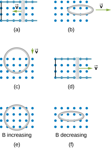
The accompanying figure shows a conducting ring at various positions as it moves through a magnetic field. What is the sense of the induced emf for each of those positions?
As the loop enters, the induced emf creates a CCW current while as the loop leaves the induced emf creates a CW current. While the loop is fully inside the magnetic field, there is no flux change and therefore no induced current.
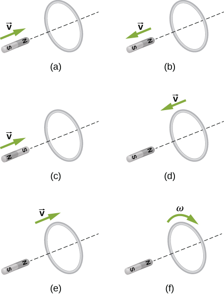
State the direction of the induced current for each case shown below, observing from the side of the magnet.
a. CCW viewed from the magnet; b. CW viewed from the magnet; c. CW viewed from the magnet; d. CCW viewed from the magnet; e. CW viewed from the magnet; f. no current
A single-turn circular loop of wire of radius 50 mm lies in a plane perpendicular to a spatially uniform magnetic field. During a 0.10-s time interval, the magnitude of the field increases uniformly from 200 to 300 mT. (a) Determine the emf induced in the loop. (b) If the magnetic field is directed out of the page, what is the direction of the current induced in the loop?
a.
; b. CCW from the same view as the magnetic field
When a magnetic field is first turned on, the flux through a 20-turn loop varies with time according to
where
is in milliwebers,
t is in seconds, and the loop is in the plane of the page with the unit normal pointing outward. (a) What is the emf induced in the loop as a function of time? What is the direction of the induced current at (b)
t = 0, (c) 0.10, (d) 1.0, and (e) 2.0 s?
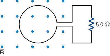
The magnetic flux through the loop shown in the accompanying figure varies with time according to
where
is in milliwebers. What are the direction and magnitude of the current through the
resistor at (a)
; (b)
and (c)
a. 150 A downward through the resistor; b. 232 A upward through the resistor; c. 0.093 A downward through the resistor