

| << Chapter < Page | Chapter >> Page > |
From Ampère’s law, this equals the total current passing through any surface bounded by the path of integration.
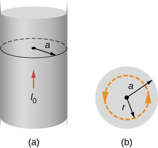
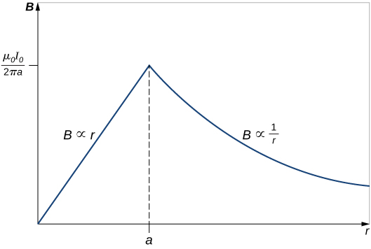
Consider first a circular path that is inside the wire such as that shown in part (a) of [link] . We need the current I passing through the area enclosed by the path. It’s equal to the current density J times the area enclosed. Since the current is uniform, the current density inside the path equals the current density in the whole wire, which is Therefore the current I passing through the area enclosed by the path is
We can consider this ratio because the current density J is constant over the area of the wire. Therefore, the current density of a part of the wire is equal to the current density in the whole area. Using Ampère’s law, we obtain
and the magnetic field inside the wire is
Outside the wire, the situation is identical to that of the infinite thin wire of the previous example; that is,
The variation of B with r is shown in [link] .

This result is similar to how Gauss’s law for electrical charges behaves inside a uniform charge distribution, except that Gauss’s law for electrical charges has a uniform volume distribution of charge, whereas Ampère’s law here has a uniform area of current distribution. Also, the drop-off outside the thick wire is similar to how an electric field drops off outside of a linear charge distribution, since the two cases have the same geometry and neither case depends on the configuration of charges or currents once the loop is outside the distribution.
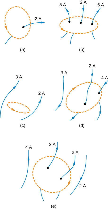
(b) The only current to consider in this problem is 2A because it is the only current inside the loop. The right-hand rule shows us the current going downward through the loop is in the positive direction. Therefore, the answer is
(c) The right-hand rule shows us the current going downward through the loop is in the positive direction. There are of current going downward and –3 A going upward. Therefore, the total current is 9 A and
Check Your Understanding Consider using Ampère’s law to calculate the magnetic fields of a finite straight wire and of a circular loop of wire. Why is it not useful for these calculations?
In these cases the integrals around the Ampèrian loop are very difficult because there is no symmetry, so this method would not be useful.
Is Ampère’s law valid for all closed paths? Why isn’t it normally useful for calculating a magnetic field?
Ampère’s law is valid for all closed paths, but it is not useful for calculating fields when the magnetic field produced lacks symmetry that can be exploited by a suitable choice of path.
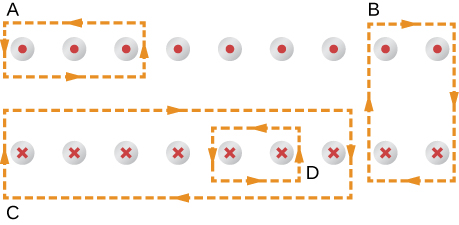
A current I flows around the rectangular loop shown in the accompanying figure. Evaluate for the paths A , B , C , and D .
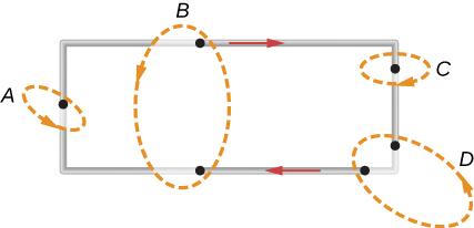
a. b. 0; c. d. 0
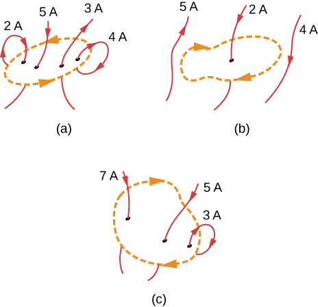
Evaluate for each of the cases shown in the accompanying figure.
The coil whose lengthwise cross section is shown in the accompanying figure carries a current I and has N evenly spaced turns distributed along the length l. Evaluate for the paths indicated.
a. b. 0; c. d.
A superconducting wire of diameter 0.25 cm carries a current of 1000 A. What is the magnetic field just outside the wire?
A long, straight wire of radius R carries a current I that is distributed uniformly over the cross-section of the wire. At what distance from the axis of the wire is the magnitude of the magnetic field a maximum?
at the radius R
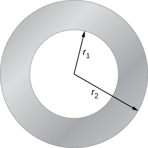
The accompanying figure shows a cross-section of a long, hollow, cylindrical conductor of inner radius and outer radius A 50-A current distributed uniformly over the cross-section flows into the page. Calculate the magnetic field at
A long, solid, cylindrical conductor of radius 3.0 cm carries a current of 50 A distributed uniformly over its cross-section. Plot the magnetic field as a function of the radial distance r from the center of the conductor.
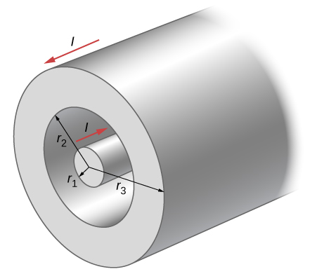
A portion of a long, cylindrical coaxial cable is shown in the accompanying figure. A current I flows down the center conductor, and this current is returned in the outer conductor. Determine the magnetic field in the regions (a) (b) (c) and (d) Assume that the current is distributed uniformly over the cross sections of the two parts of the cable.
Notification Switch
Would you like to follow the 'University physics volume 2' conversation and receive update notifications?

|
|

|
|

|
|

|
|
|
|
|

|
|

|
|

|
|

|
|

|