<< Chapter < Page Chapter >> Page >

As the charge on the capacitor increases, the current through the resistor decreases, as shown in [link] (b). The current through the resistor can be found by taking the time derivative of the charge.

I ( t ) = d q d t = d d t [ C ε ( 1 e t R C ) ] , I ( t ) = C ε ( 1 R C ) e t R C = ε R e t R C = I o e t R C ,
I ( t ) = I 0 e t / τ .

At time t = 0.00 s , the current through the resistor is I 0 = ε R . As time approaches infinity, the current approaches zero. At time t = τ , the current through the resistor is I ( t = τ ) = I 0 e −1 = 0.368 I 0 .

The figure shows four graphs of capacitor charging, with time on the x-axis. Parts a shows charge of the capacitor on the y-axis, the value increases from 0 to Cε and is equal to 0.632 Cε after 1 τ. Parts b shows current of the resistor on the y-axis, the value decreases from I subscript 0 to 0 and is equal to 0.368 I subscript 0 after 1 τ. Parts c shows voltage of the capacitor on the y-axis, the value increases from 0 to ε and is equal to 0.632 ε after 1 τ. Parts d shows voltage of the resistor on the y-axis, the value decreases from ε to 0 and is equal to 0.368 ε after 1 τ.
(a) Charge on the capacitor versus time as the capacitor charges. (b) Current through the resistor versus time. (c) Voltage difference across the capacitor. (d) Voltage difference across the resistor.

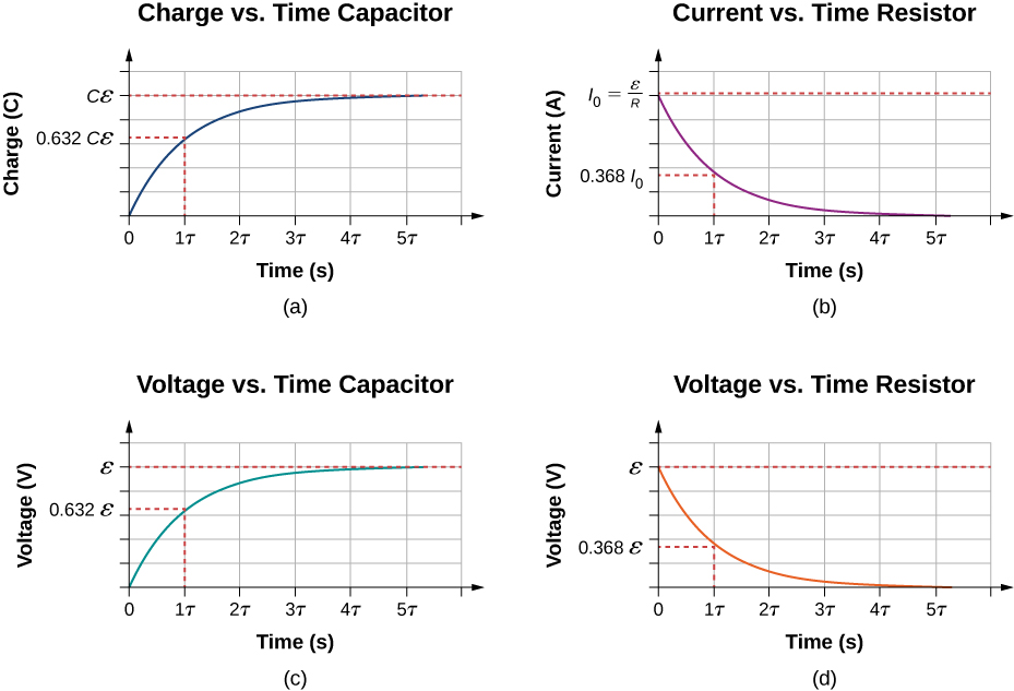
[link] (c) and [link] (d) show the voltage differences across the capacitor and the resistor, respectively. As the charge on the capacitor increases, the current decreases, as does the voltage difference across the resistor V R ( t ) = ( I 0 R ) e t / τ = ε e t / τ . The voltage difference across the capacitor increases as V C ( t ) = ε ( 1 e t / τ ) .

Discharging a capacitor

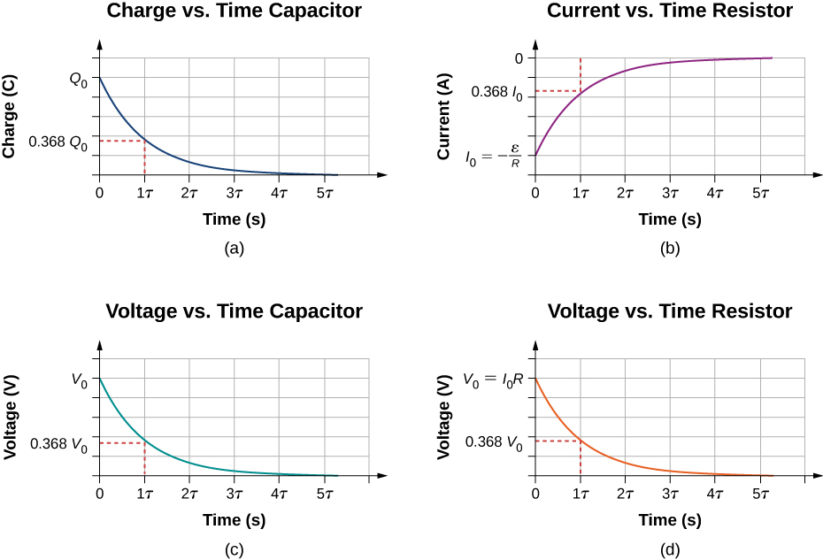
When the switch in [link] (a) is moved to position B , the circuit reduces to the circuit in part (c), and the charged capacitor is allowed to discharge through the resistor. A graph of the charge on the capacitor as a function of time is shown in [link] (a). Using Kirchhoff’s loop rule to analyze the circuit as the capacitor discharges results in the equation V R V c = 0 , which simplifies to I R + q C = 0 . Using the definition of current d q d t R = q C and integrating the loop equation yields an equation for the charge on the capacitor as a function of time:

q ( t ) = Q e t / τ .

Here, Q is the initial charge on the capacitor and τ = R C is the time constant of the circuit. As shown in the graph, the charge decreases exponentially from the initial charge, approaching zero as time approaches infinity.

The current as a function of time can be found by taking the time derivative of the charge:

I ( t ) = Q R C e t / τ .

The negative sign shows that the current flows in the opposite direction of the current found when the capacitor is charging. [link] (b) shows an example of a plot of charge versus time and current versus time. A plot of the voltage difference across the capacitor and the voltage difference across the resistor as a function of time are shown in parts (c) and (d) of the figure. Note that the magnitudes of the charge, current, and voltage all decrease exponentially, approaching zero as time increases.

The figure shows four graphs of capacitor discharging, with time on the x-axis. Parts a shows charge of the capacitor on the y-axis, the value decreases from Q subscript 0 to 0 and is equal to 0.368 Q subscript 0 after 1 τ. Parts b shows current of the resistor on the y-axis, the value increases from I subscript 0 to 0 and is equal to 0.368 I subscript 0 after 1 τ. Parts c shows voltage of the capacitor on the y-axis, the value decreases from V subscript 0 to 0 and is equal to 0.368 V subscript 0 after 1 τ. Parts d shows voltage of the resistor on the y-axis, the value decreases from V subscript 0 to 0 and is equal to 0.368 V subscript 0 after 1 τ.
(a) Charge on the capacitor versus time as the capacitor discharges. (b) Current through the resistor versus time. (c) Voltage difference across the capacitor. (d) Voltage difference across the resistor.

Now we can explain why the flash camera mentioned at the beginning of this section takes so much longer to charge than discharge: The resistance while charging is significantly greater than while discharging. The internal resistance of the battery accounts for most of the resistance while charging. As the battery ages, the increasing internal resistance makes the charging process even slower.

The relaxation oscillator

One application of an RC circuit is the relaxation oscillator, as shown below. The relaxation oscillator consists of a voltage source, a resistor, a capacitor, and a neon lamp. The neon lamp acts like an open circuit (infinite resistance) until the potential difference across the neon lamp reaches a specific voltage. At that voltage, the lamp acts like a short circuit (zero resistance), and the capacitor discharges through the neon lamp and produces light. In the relaxation oscillator shown, the voltage source charges the capacitor until the voltage across the capacitor is 80 V. When this happens, the neon in the lamp breaks down and allows the capacitor to discharge through the lamp, producing a bright flash. After the capacitor fully discharges through the neon lamp, it begins to charge again, and the process repeats. Assuming that the time it takes the capacitor to discharge is negligible, what is the time interval between flashes?

Practice Key Terms 1

Get Jobilize Job Search Mobile App in your pocket Now!

Get it on Google Play Download on the App Store Now


Source:  OpenStax, University physics volume 2. OpenStax CNX. Oct 06, 2016 Download for free at http://cnx.org/content/col12074/1.3
Google Play and the Google Play logo are trademarks of Google Inc.

Notification Switch

Would you like to follow the 'University physics volume 2' conversation and receive update notifications?

Ask