

| << Chapter < Page | Chapter >> Page > |
Consider a power plant located 25 km outside a town delivering 50 MW of power to the town. The transmission lines are made of aluminum cables with a cross-sectional area. Find the loss of power in the transmission lines if it is transmitted at (a) 200 kV (rms) and (b) 120 V (rms).
a. ; b.
Neon signs require 12-kV for their operation. A transformer is to be used to change the voltage from 220-V (rms) ac to 12-kV (rms) ac. What must the ratio be of turns in the secondary winding to the turns in the primary winding? (b) What is the maximum rms current the neon lamps can draw if the fuse in the primary winding goes off at 0.5 A? (c) How much power is used by the neon sign when it is drawing the maximum current allowed by the fuse in the primary winding?
The 335-kV ac electricity from a power transmission line is fed into the primary winding of a transformer. The ratio of the number of turns in the secondary winding to the number in the primary winding is . (a) What voltage is induced in the secondary winding? (b) What is unreasonable about this result? (c) Which assumption or premise is responsible?
a. 335 MV; b. the result is way too high, well beyond the breakdown voltage of air over reasonable distances; c. the input voltage is too high
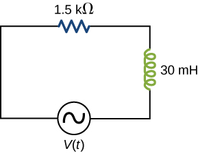
A resistor and 30-mH inductor are connected in series, as shown below, across a 120-V (rms) ac power source oscillating at 60-Hz frequency. (a) Find the current in the circuit. (b) Find the voltage drops across the resistor and inductor. (c) Find the impedance of the circuit. (d) Find the power dissipated in the resistor. (e) Find the power dissipated in the inductor. (f) Find the power produced by the source.
A resistor, capacitor, and 30-mH inductor are connected in series with an ac source of amplitude 10 V and frequency 125 Hz. (a) What is the impedance of the circuit? (b) What is the amplitude of the current in the circuit? (c) What is the phase constant of the current? Is it leading or lagging the source voltage? (d) Write voltage drops across the resistor, capacitor, and inductor and the source voltage as a function of time. (e) What is the power factor of the circuit? (f) How much energy is used by the resistor in 2.5 s?
a.
; b. 0.5 A; c.
, lagging;
d.
e. 0.995; f. 6.25 J
A resistor, capacitor, and 2.5-H inductor are connected in series with an ac source of amplitude 10 V and variable angular frequency . (a) What is the value of the resonance frequency ? (b) What is the amplitude of the current if ? (c) What is the phase constant of the current when ? Is it leading or lagging the source voltage, or is it in phase? (d) Write an equation for the voltage drop across the resistor as a function of time when . (e) What is the power factor of the circuit when ? (f) How much energy is used up by the resistor in 2.5 s when ?
Find the reactances of the following capacitors and inductors in ac circuits with the given frequencies in each case: (a) 2-mH inductor with a frequency 60-Hz of the ac circuit; (b) 2-mH inductor with a frequency 600-Hz of the ac circuit; (c) 20-mH inductor with a frequency 6-Hz of the ac circuit; (d) 20-mH inductor with a frequency 60-Hz of the ac circuit; (e) 2-mF capacitor with a frequency 60-Hz of the ac circuit; and (f) 2-mF capacitor with a frequency 600-Hz of the AC circuit.
a. ; b. ; c. ; d. ; e. ; f.
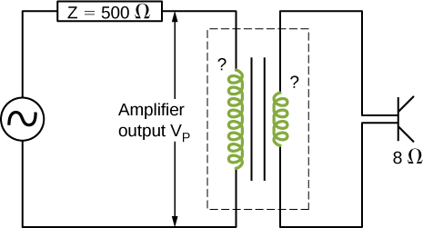
An output impedance of an audio amplifier has an impedance of and has a mismatch with a low-impedance loudspeaker. You are asked to insert an appropriate transformer to match the impedances. What turns ratio will you use, and why? Use the simplified circuit shown below.
Show that the SI unit for capacitive reactance is the ohm. Show that the SI unit for inductive reactance is also the ohm.
The units as written for inductive reactance [link] are . Radians can be ignored in unit analysis. The Henry can be defined as . Combining these together results in a unit of for reactance.
A coil with a self-inductance of 16 mH and a resistance of is connected to an ac source whose frequency can be varied. At what frequency will the voltage across the coil lead the current through the coil by
An RLC series circuit consists of a resistor, a capacitor, and a 120-mH inductor whose coil has a resistance of . The source for the circuit has an rms emf of 240 V at a frequency of 60 Hz. Calculate the rms voltages across the (a) resistor, (b) capacitor, and (c) inductor.
a. 156 V; b. 42 V; c. 154 V
An RLC series circuit consists of a resistor, an capacitor, and a 50-mH inductor. A 110-V (rms) source of variable frequency is connected across the combination. What is the power output of the source when its frequency is set to one-half the resonant frequency of the circuit?
Shown below are two circuits that act as crude high-pass filters. The input voltage to the circuits is , and the output voltage is (a) Show that for the capacitor circuit,
and for the inductor circuit,
(b) Show that for high frequencies, but for low frequencies,
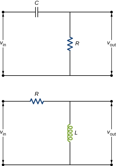
a. and ; b. and
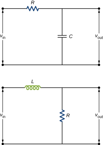
The two circuits shown below act as crude low-pass filters. The input voltage to the circuits is , and the output voltage is (a) Show that for the capacitor circuit,
and for the inductor circuit,
(b) Show that for low frequencies, but for high frequencies,
Notification Switch
Would you like to follow the 'University physics volume 2' conversation and receive update notifications?

|
|

|
|

|
|

|
|

|
|

|
|

|
|

|
|

|
|

|