

| << Chapter < Page | Chapter >> Page > |
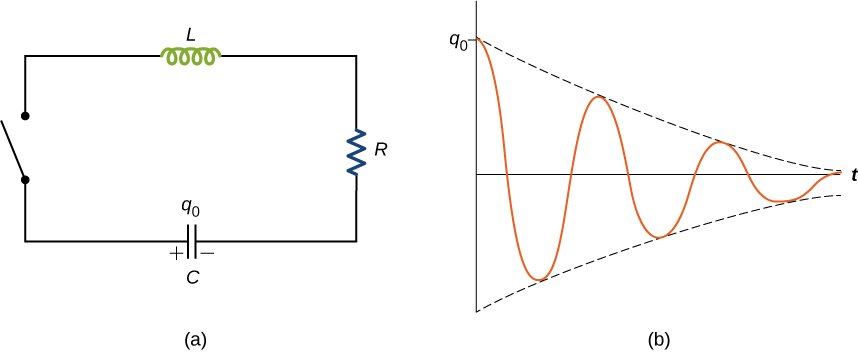
When the switch is closed in the RLC circuit of [link] (a), the capacitor begins to discharge and electromagnetic energy is dissipated by the resistor at a rate . With U given by [link] , we have
where i and q are time-dependent functions. This reduces to
This equation is analogous to
which is the equation of motion for a damped mass-spring system (you first encountered this equation in Oscillations ). As we saw in that chapter, it can be shown that the solution to this differential equation takes three forms, depending on whether the angular frequency of the undamped spring is greater than, equal to, or less than b /2 m . Therefore, the result can be underdamped , critically damped , or overdamped . By analogy, the solution q ( t ) to the RLC differential equation has the same feature. Here we look only at the case of under-damping. By replacing m by L , b by R , k by 1/ C , and x by q in [link] , and assuming , we obtain
where the angular frequency of the oscillations is given by
This underdamped solution is shown in [link] (b). Notice that the amplitude of the oscillations decreases as energy is dissipated in the resistor. [link] can be confirmed experimentally by measuring the voltage across the capacitor as a function of time. This voltage, multiplied by the capacitance of the capacitor, then gives q ( t ).
Try an interactive circuit construction kit that allows you to graph current and voltage as a function of time. You can add inductors and capacitors to work with any combination of R , L , and C circuits with both dc and ac sources.
Try out a circuit-based java applet website that has many problems with both dc and ac sources that will help you practice circuit problems.
Check Your Understanding In an RLC circuit, (a) Is the circuit underdamped, critically damped, or overdamped? (b) If the circuit starts oscillating with a charge of on the capacitor, how much energy has been dissipated in the resistor by the time the oscillations cease?
a. overdamped; b. 0.75 J
| Mutual inductance by flux | |
| Mutual inductance in circuits | |
| Self-inductance in terms of magnetic flux | |
| Self-inductance in terms of emf | |
| Self-inductance of a solenoid | |
| Self-inductance of a toroid | |
| Energy stored in an inductor | |
| Current as a function of time for a RL circuit | |
| Time constant for a RL circuit | |
| Charge oscillation in LC circuits | |
| Angular frequency in LC circuits | |
| Current oscillations in LC circuits | |
| Charge as a function of time in RLC circuit | |
| Angular frequency in RLC circuit |
Notification Switch
Would you like to follow the 'University physics volume 2' conversation and receive update notifications?

|
|

|
|

|
|

|
|

|
|

|
|

|
|

|
|

|
|

|