<< Chapter < Page Chapter >> Page >
By the end of this section, you will be able to:
  • Analyze circuits that have an inductor and resistor in series
  • Describe how current and voltage exponentially grow or decay based on the initial conditions

A circuit with resistance and self-inductance is known as an RL circuit. [link] (a) shows an RL circuit consisting of a resistor, an inductor, a constant source of emf, and switches S 1 and S 2 . When S 1 is closed, the circuit is equivalent to a single-loop circuit consisting of a resistor and an inductor connected across a source of emf ( [link] (b)). When S 1 is opened and S 2 is closed, the circuit becomes a single-loop circuit with only a resistor and an inductor ( [link] (c)).

Figure a shows a resistor R and an inductor L connected in series with two switches which are parallel to each other. Both switches are currently open. Closing switch S1 would connect R and L in series with a battery, whose positive terminal is towards L. Closing switch S2 would form a closed loop of R and L, without the battery. Figure b shows a closed circuit with R, L and the battery in series. The side of L towards the battery, is at positive potential. Current flows from the positive end of L, through it, to the negative end. Figure c shows R and L connected in series. The potential across L is reversed, but the current flows in the same direction as in figure b.
(a) An RL circuit with switches S 1 and S 2 . (b) The equivalent circuit with S 1 closed and S 2 open. (c) The equivalent circuit after S 1 is opened and S 2 is closed.

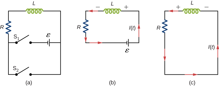
We first consider the RL circuit of [link] (b). Once S 1 is closed and S 2 is open, the source of emf produces a current in the circuit. If there were no self-inductance in the circuit, the current would rise immediately to a steady value of ε / R . However, from Faraday’s law, the increasing current produces an emf V L = L ( d I / d t ) across the inductor. In accordance with Lenz’s law, the induced emf counteracts the increase in the current and is directed as shown in the figure. As a result, I(t) starts at zero and increases asymptotically to its final value.

Applying Kirchhoff’s loop rule to this circuit, we obtain

ε L d I d t I R = 0 ,

which is a first-order differential equation for I(t) . Notice its similarity to the equation for a capacitor and resistor in series (See RC Circuits ). Similarly, the solution to [link] can be found by making substitutions in the equations relating the capacitor to the inductor. This gives

I ( t ) = ε R ( 1 e R t / L ) = ε R ( 1 e t / τ L ) ,

where

τ L = L / R

is the inductive time constant    of the circuit.

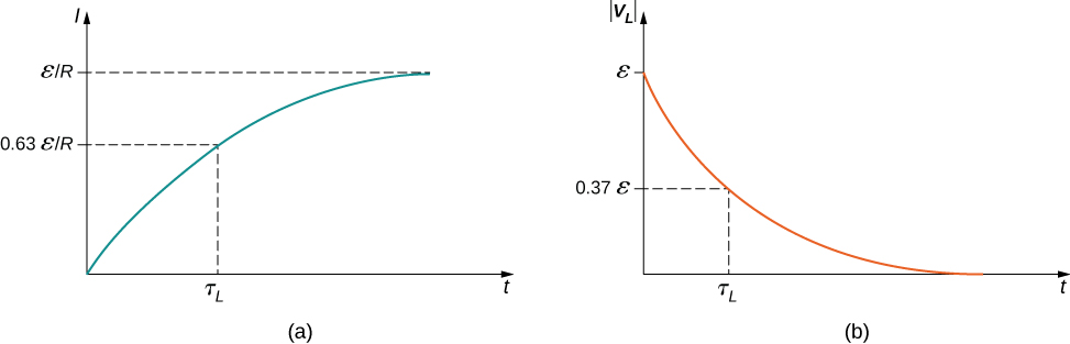
The current I(t) is plotted in [link] (a). It starts at zero, and as t , I(t) approaches ε / R asymptotically. The induced emf V L ( t ) is directly proportional to dI / dt , or the slope of the curve. Hence, while at its greatest immediately after the switches are thrown, the induced emf decreases to zero with time as the current approaches its final value of ε / R . The circuit then becomes equivalent to a resistor connected across a source of emf.

Figure a shows the graph of electric current I versus time t. Current increases with time in a curve which flattens out at epsilon I R. At t equal to tau subscript L, the value of I is 0.63 epsilon I R. Figure b shows the graph of magnitude of induced voltage, mod V subscript L, versus time t. Mod V subscript L starts at value epsilon and decreases with time till the curve reaches zero. At t equal to tau subscript L, the value of I is 0.37 epsilon.
Time variation of (a) the electric current and (b) the magnitude of the induced voltage across the coil in the circuit of [link] (b).

The energy stored in the magnetic field of an inductor is

U L = 1 2 L I 2 .

Thus, as the current approaches the maximum current ε / R , the stored energy in the inductor increases from zero and asymptotically approaches a maximum of L ( ε / R ) 2 / 2 .

The time constant τ L tells us how rapidly the current increases to its final value. At t = τ L , the current in the circuit is, from [link] ,

I ( τ L ) = ε R ( 1 e −1 ) = 0.63 ε R ,

which is 63 % of the final value ε / R . The smaller the inductive time constant τ L = L / R , the more rapidly the current approaches ε / R .

We can find the time dependence of the induced voltage across the inductor in this circuit by using V L ( t ) = L ( d I / d t ) and [link] :

V L ( t ) = L d I d t = ε e t / τ L .

The magnitude of this function is plotted in [link] (b). The greatest value of L ( d I / d t ) is ε ; it occurs when dI/dt is greatest, which is immediately after S 1 is closed and S 2 is opened. In the approach to steady state, dI/dt decreases to zero. As a result, the voltage across the inductor also vanishes as t .

Questions & Answers

what is biology
Hajah Reply
the study of living organisms and their interactions with one another and their environments
AI-Robot
what is biology
Victoria Reply
HOW CAN MAN ORGAN FUNCTION
Alfred Reply
the diagram of the digestive system
Assiatu Reply
allimentary cannel
Ogenrwot
How does twins formed
William Reply
They formed in two ways first when one sperm and one egg are splited by mitosis or two sperm and two eggs join together
Oluwatobi
what is genetics
Josephine Reply
Genetics is the study of heredity
Misack
how does twins formed?
Misack
What is manual
Hassan Reply
discuss biological phenomenon and provide pieces of evidence to show that it was responsible for the formation of eukaryotic organelles
Joseph Reply
what is biology
Yousuf Reply
the study of living organisms and their interactions with one another and their environment.
Wine
discuss the biological phenomenon and provide pieces of evidence to show that it was responsible for the formation of eukaryotic organelles in an essay form
Joseph Reply
what is the blood cells
Shaker Reply
list any five characteristics of the blood cells
Shaker
lack electricity and its more savely than electronic microscope because its naturally by using of light
Abdullahi Reply
advantage of electronic microscope is easily and clearly while disadvantage is dangerous because its electronic. advantage of light microscope is savely and naturally by sun while disadvantage is not easily,means its not sharp and not clear
Abdullahi
cell theory state that every organisms composed of one or more cell,cell is the basic unit of life
Abdullahi
is like gone fail us
DENG
cells is the basic structure and functions of all living things
Ramadan
What is classification
ISCONT Reply
is organisms that are similar into groups called tara
Yamosa
in what situation (s) would be the use of a scanning electron microscope be ideal and why?
Kenna Reply
A scanning electron microscope (SEM) is ideal for situations requiring high-resolution imaging of surfaces. It is commonly used in materials science, biology, and geology to examine the topography and composition of samples at a nanoscale level. SEM is particularly useful for studying fine details,
Hilary
cell is the building block of life.
Condoleezza Reply
Got questions? Join the online conversation and get instant answers!
Jobilize.com Reply
Practice Key Terms 1

Get Jobilize Job Search Mobile App in your pocket Now!

Get it on Google Play Download on the App Store Now


Source:  OpenStax, University physics volume 2. OpenStax CNX. Oct 06, 2016 Download for free at http://cnx.org/content/col12074/1.3
Google Play and the Google Play logo are trademarks of Google Inc.

Notification Switch

Would you like to follow the 'University physics volume 2' conversation and receive update notifications?

Ask