<< Chapter < Page Chapter >> Page >
By the end of this section, you will be able to:
  • Evaluate the net force on a current loop in an external magnetic field
  • Evaluate the net torque on a current loop in an external magnetic field
  • Define the magnetic dipole moment of a current loop

Motors are the most common application of magnetic force on current-carrying wires. Motors contain loops of wire in a magnetic field. When current is passed through the loops, the magnetic field exerts torque on the loops, which rotates a shaft. Electrical energy is converted into mechanical work in the process. Once the loop’s surface area is aligned with the magnetic field, the direction of current is reversed, so there is a continual torque on the loop ( [link] ). This reversal of the current is done with commutators and brushes. The commutator is set to reverse the current flow at set points to keep continual motion in the motor. A basic commutator has three contact areas to avoid and dead spots where the loop would have zero instantaneous torque at that point. The brushes press against the commutator, creating electrical contact between parts of the commutator during the spinning motion.

A schematic of a d c motor consisting of a magnet with a horizontal gap, a power supply with leads attached to brushes, an a wire is bent into a rectangular loop. The ends of the wire are attached to contacts that connect to the brushes of the power supply when the loop is horizontal. When the loop is vertical, they align with the gap between the contacts. The north pole of the magnet is on the left, the south pole on the right. Figure a: The loop is horizontal and the brushes make contact with the loop. A clockwise (looking down) current flows through the loop, so the current in the left segment of the loop flows into the page, and the current in the right segment flows out of the page. The magnetic force on the left segment is down, and on the right segment is up. The loop rotates counterclockwise (looking into the page.) Figure b: The loop is vertical. The brushes are not in contact with the loop. No current flows and no forces are exerted.
A simplified version of a dc electric motor. (a) The rectangular wire loop is placed in a magnetic field. The forces on the wires closest to the magnetic poles (N and S) are opposite in direction as determined by the right-hand rule-1. Therefore, the loop has a net torque and rotates to the position shown in (b). (b) The brushes now touch the commutator segments so that no current flows through the loop. No torque acts on the loop, but the loop continues to spin from the initial velocity given to it in part (a). By the time the loop flips over, current flows through the wires again but now in the opposite direction, and the process repeats as in part (a). This causes continual rotation of the loop.

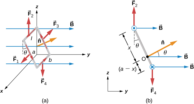
In a uniform magnetic field, a current-carrying loop of wire, such as a loop in a motor, experiences both forces and torques on the loop. [link] shows a rectangular loop of wire that carries a current I and has sides of lengths a and b . The loop is in a uniform magnetic field: B = B j ^ . The magnetic force on a straight current-carrying wire of length l is given by I l × B . To find the net force on the loop, we have to apply this equation to each of the four sides. The force on side 1 is

F 1 = I a B sin ( 90 ° θ ) i ^ = I a B cos θ i ^

where the direction has been determined with the RHR-1. The current in side 3 flows in the opposite direction to that of side 1, so

F 3 = I a B sin ( 90 ° + θ ) i ^ = I a B cos θ i ^ .

The currents in sides 2 and 4 are perpendicular to B and the forces on these sides are

F 2 = I b B k ^ , F 4 = I b B k ^ .

We can now find the net force on the loop:

F net = F 1 + F 2 + F 3 + F 4 = 0 .

Although this result ( Σ F = 0 ) has been obtained for a rectangular loop, it is far more general and holds for current-carrying loops of arbitrary shapes; that is, there is no net force on a current loop in a uniform magnetic field.

An illustration of a rectangular loop carrying a current I. The current in the loop is counterclockwise when viewed from the positive y direction looking toward the origin. The loop is in a uniform magnetic field, B, that is pointing to the right. Figure a shows a 3 dimensional view of the loop. The top and bottom sides are parallel to the x axis and have length b. The top side is at y=0 and positive z with current in the positive x direction. The bottom side is at a positive y and z=0 and has current in the negative x direction. The remaining two sides have length b. One is at x=0 and has current going up, and one is at positive x and has current going up. These sides are tilted at an angle theta at the top with respect to the z axis. The direction of the unit vector n hat normal to the area of the rectangular loop is shown. The forces on each of the sides are also shown. F 1 is the force on the tilted side at positive x, and points in the positive x direction. F 2 is the force on the top side and points up. F 3 is the force on the tilted side at x=0 and points in the negative x direction. F 4 is the force on the bottom and points down. Figure b shows a side view of the loop, so that we are looking at the y z plane and see only the tilted side, which makes an angle of theta with the vertical at the top. The current is coming out at us at the top of the loop, and the current is going into the page at the bottom. The force F 2 on the top is up, the force F 4 on the bottom is down. The n hat vector points up and to the right, at an angle of theta to the field B. The pivot point O about which we are calculating the torque is shown a distance x from the top of the loop, and a-x from the bottom.
(a) A rectangular current loop in a uniform magnetic field is subjected to a net torque but not a net force. (b) A side view of the coil.
Practice Key Terms 3

Get Jobilize Job Search Mobile App in your pocket Now!

Get it on Google Play Download on the App Store Now


Source:  OpenStax, University physics volume 2. OpenStax CNX. Oct 06, 2016 Download for free at http://cnx.org/content/col12074/1.3
Google Play and the Google Play logo are trademarks of Google Inc.

Notification Switch

Would you like to follow the 'University physics volume 2' conversation and receive update notifications?

Ask