

| << Chapter < Page | Chapter >> Page > |
Let’s examine some steps in this procedure more closely. When locating the junctions in the circuit, do not be concerned about the direction of the currents. If the direction of current flow is not obvious, choosing any direction is sufficient as long as at least one current points into the junction and at least one current points out of the junction. If the arrow is in the opposite direction of the conventional current flow, the result for the current in question will be negative but the answer will still be correct.
The number of nodes depends on the circuit. Each current should be included in a node and thus included in at least one junction equation. Do not include nodes that are not linearly independent, meaning nodes that contain the same information.
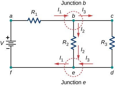
Consider [link] . There are two junctions in this circuit: Junction b and Junction e . Points a , c , d , and f are not junctions, because a junction must have three or more connections. The equation for Junction b is , and the equation for Junction e is . These are equivalent equations, so it is necessary to keep only one of them.
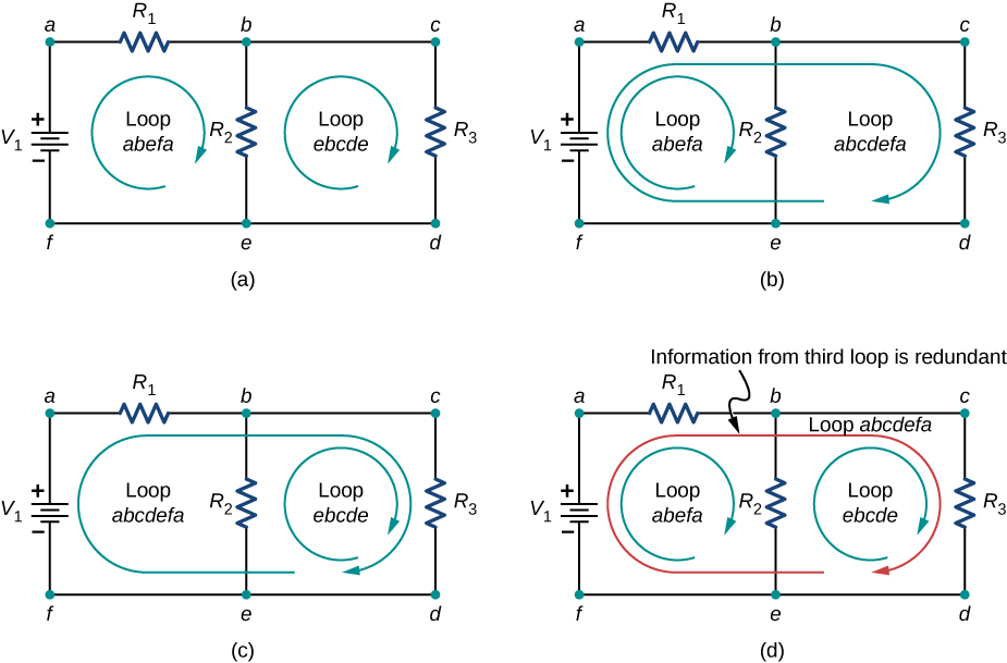
When choosing the loops in the circuit, you need enough loops so that each component is covered once, without repeating loops. [link] shows four choices for loops to solve a sample circuit; choices (a), (b), and (c) have a sufficient amount of loops to solve the circuit completely. Option (d) reflects more loops than necessary to solve the circuit.
Consider the circuit in [link] (a). Let us analyze this circuit to find the current through each resistor. First, label the circuit as shown in part (b).
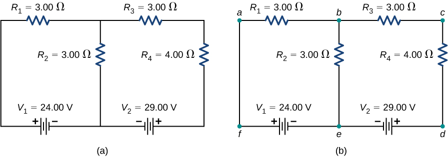
Next, determine the junctions. In this circuit, points b and e each have three wires connected, making them junctions. Start to apply Kirchhoff’s junction rule by drawing arrows representing the currents and labeling each arrow, as shown in [link] (b). Junction b shows that and Junction e shows that . Since Junction e gives the same information of Junction b , it can be disregarded. This circuit has three unknowns, so we need three linearly independent equations to analyze it.
Next we need to choose the loops. In [link] , Loop abefa includes the voltage source and resistors and . The loop starts at point a , then travels through points b , e , and f , and then back to point a . The second loop, Loop ebcde , starts at point e and includes resistors and , and the voltage source .
Notification Switch
Would you like to follow the 'University physics volume 2' conversation and receive update notifications?

|
|
|
|
|

|
|

|
|

|
|

|
|

|
|

|
|

|
|

|