

| << Chapter < Page | Chapter >> Page > |
In Current and Resistance , we described the term ‘resistance’ and explained the basic design of a resistor. Basically, a resistor limits the flow of charge in a circuit and is an ohmic device where Most circuits have more than one resistor. If several resistors are connected together and connected to a battery, the current supplied by the battery depends on the equivalent resistance of the circuit.
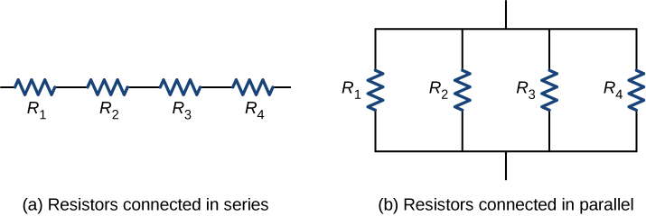
The equivalent resistance of a combination of resistors depends on both their individual values and how they are connected. The simplest combinations of resistors are series and parallel connections ( [link] ). In a series circuit , the output current of the first resistor flows into the input of the second resistor; therefore, the current is the same in each resistor. In a parallel circuit , all of the resistor leads on one side of the resistors are connected together and all the leads on the other side are connected together. In the case of a parallel configuration, each resistor has the same potential drop across it, and the currents through each resistor may be different, depending on the resistor. The sum of the individual currents equals the current that flows into the parallel connections.
Resistors are said to be in series whenever the current flows through the resistors sequentially. Consider [link] , which shows three resistors in series with an applied voltage equal to Since there is only one path for the charges to flow through, the current is the same through each resistor. The equivalent resistance of a set of resistors in a series connection is equal to the algebraic sum of the individual resistances.
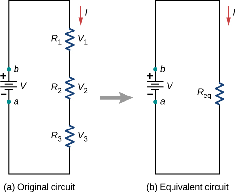
In [link] , the current coming from the voltage source flows through each resistor, so the current through each resistor is the same. The current through the circuit depends on the voltage supplied by the voltage source and the resistance of the resistors. For each resistor, a potential drop occurs that is equal to the loss of electric potential energy as a current travels through each resistor. According to Ohm’s law, the potential drop V across a resistor when a current flows through it is calculated using the equation where I is the current in amps (A) and R is the resistance in ohms Since energy is conserved, and the voltage is equal to the potential energy per charge, the sum of the voltage applied to the circuit by the source and the potential drops across the individual resistors around a loop should be equal to zero:
Notification Switch
Would you like to follow the 'University physics volume 2' conversation and receive update notifications?

|
|

|
|

|
|

|
|

|
|

|
|

|
|

|
|

|
|

|