<< Chapter < Page Chapter >> Page >
By the end of the section, you will be able to:
  • Explain the rules for drawing a free-body diagram
  • Construct free-body diagrams for different situations

The first step in describing and analyzing most phenomena in physics involves the careful drawing of a free-body diagram. Free-body diagrams have been used in examples throughout this chapter. Remember that a free-body diagram must only include the external forces acting on the body of interest. Once we have drawn an accurate free-body diagram, we can apply Newton’s first law if the body is in equilibrium (balanced forces; that is, F net = 0 ) or Newton’s second law if the body is accelerating (unbalanced force; that is, F net 0 ).

In Forces , we gave a brief problem-solving strategy to help you understand free-body diagrams. Here, we add some details to the strategy that will help you in constructing these diagrams.

Problem-solving strategy: constructing free-body diagrams

Observe the following rules when constructing a free-body diagram:

  1. Draw the object under consideration; it does not have to be artistic. At first, you may want to draw a circle around the object of interest to be sure you focus on labeling the forces acting on the object. If you are treating the object as a particle (no size or shape and no rotation), represent the object as a point. We often place this point at the origin of an xy -coordinate system.
  2. Include all forces that act on the object, representing these forces as vectors. Consider the types of forces described in Common Forces —normal force, friction, tension, and spring force—as well as weight and applied force. Do not include the net force on the object. With the exception of gravity, all of the forces we have discussed require direct contact with the object. However, forces that the object exerts on its environment must not be included. We never include both forces of an action-reaction pair.
  3. Convert the free-body diagram into a more detailed diagram showing the x - and y -components of a given force (this is often helpful when solving a problem using Newton’s first or second law). In this case, place a squiggly line through the original vector to show that it is no longer in play—it has been replaced by its x - and y -components.
  4. If there are two or more objects, or bodies, in the problem, draw a separate free-body diagram for each object.

Note: If there is acceleration, we do not directly include it in the free-body diagram; however, it may help to indicate acceleration outside the free-body diagram. You can label it in a different color to indicate that it is separate from the free-body diagram.

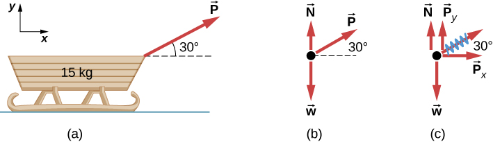
Let’s apply the problem-solving strategy in drawing a free-body diagram for a sled. In [link] (a), a sled is pulled by force P at an angle of 30 ° . In part (b), we show a free-body diagram for this situation, as described by steps 1 and 2 of the problem-solving strategy. In part (c), we show all forces in terms of their x - and y -components, in keeping with step 3.

Figure a shows a sled of 15 kg. An arrow labeled P pointing right and up forms an angle of 30 degrees with the horizontal. Figure b is a free body diagram with P, N pointing up and w pointing down. Figure c is a free body diagram with P, N, w and two components of P: Px pointing right and Py pointing up.
(a) A moving sled is shown as (b) a free-body diagram and (c) a free-body diagram with force components.

Get Jobilize Job Search Mobile App in your pocket Now!

Get it on Google Play Download on the App Store Now


Source:  OpenStax, University physics volume 1. OpenStax CNX. Sep 19, 2016 Download for free at http://cnx.org/content/col12031/1.5
Google Play and the Google Play logo are trademarks of Google Inc.

Notification Switch

Would you like to follow the 'University physics volume 1' conversation and receive update notifications?

Ask