<< Chapter < Page Chapter >> Page >

The image in most telescopes is inverted, which is unimportant for observing the stars but a real problem for other applications, such as telescopes on ships or telescopic gun sights. If an upright image is needed, Galileo’s arrangement in [link] (a) can be used. But a more common arrangement is to use a third convex lens as an eyepiece, increasing the distance between the first two and inverting the image once again as seen in [link] .
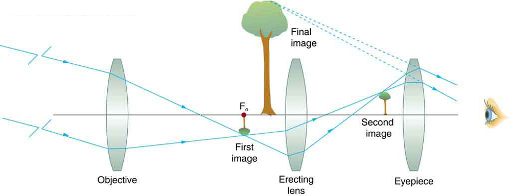
A ray diagram from left to right depicts a concave objective lens, a small inverted image of a tree, a magnified upright final image of tree, an erecting concave lens, a small upright image of a tree, concave lens as an eyepiece, and an eye to view on the same optical axis. Rays from a distant object strike the edges of the objective lens, converge at the focus of the focal point, form a small inverted image of the object and pass through the erecting lens, again forming the upright small image of the object, and finally, the rays pass through the eyepiece to the eye. Dotted lines joined backwards from the rays striking the eyepiece meet at a point where the final enlarged upright image of the object is formed.
This arrangement of three lenses in a telescope produces an upright final image. The first two lenses are far enough apart that the second lens inverts the image of the first one more time. The third lens acts as a magnifier and keeps the image upright and in a location that is easy to view.

A telescope can also be made with a concave mirror as its first element or objective, since a concave mirror acts like a convex lens as seen in [link] . Flat mirrors are often employed in optical instruments to make them more compact or to send light to cameras and other sensing devices. There are many advantages to using mirrors rather than lenses for telescope objectives. Mirrors can be constructed much larger than lenses and can, thus, gather large amounts of light, as needed to view distant galaxies, for example. Large and relatively flat mirrors have very long focal lengths, so that great angular magnification is possible.
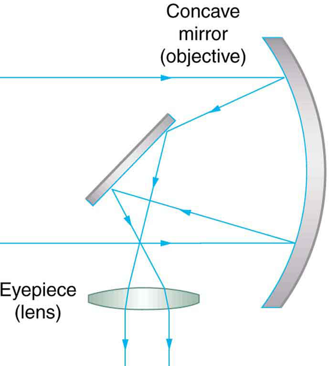
A ray diagram from left to right depicts a small diagonal mirror and a concave lens eyepiece placed parallel to each other. A large curved objective mirror is placed in front of the diagonal mirror. Parallel rays of light are falling at the edges of the objective mirror, which is curved just at the right amount to bounce all the light onto the diagonal mirror. From there, the light rays pass through the eyepiece lens, which bends the light into the eye.
A two-element telescope composed of a mirror as the objective and a lens for the eyepiece is shown. This telescope forms an image in the same manner as the two-convex-lens telescope already discussed, but it does not suffer from chromatic aberrations. Such telescopes can gather more light, since larger mirrors than lenses can be constructed.

Telescopes, like microscopes, can utilize a range of frequencies from the electromagnetic spectrum. [link] (a) shows the Australia Telescope Compact Array, which uses six 22-m antennas for mapping the southern skies using radio waves. [link] (b) shows the focusing of x rays on the Chandra X-ray Observatory—a satellite orbiting earth since 1999 and looking at high temperature events as exploding stars, quasars, and black holes. X rays, with much more energy and shorter wavelengths than RF and light, are mainly absorbed and not reflected when incident perpendicular to the medium. But they can be reflected when incident at small glancing angles, much like a rock will skip on a lake if thrown at a small angle. The mirrors for the Chandra consist of a long barrelled pathway and 4 pairs of mirrors to focus the rays at a point 10 meters away from the entrance. The mirrors are extremely smooth and consist of a glass ceramic base with a thin coating of metal (iridium). Four pairs of precision manufactured mirrors are exquisitely shaped and aligned so that x rays ricochet off the mirrors like bullets off a wall, focusing on a spot.
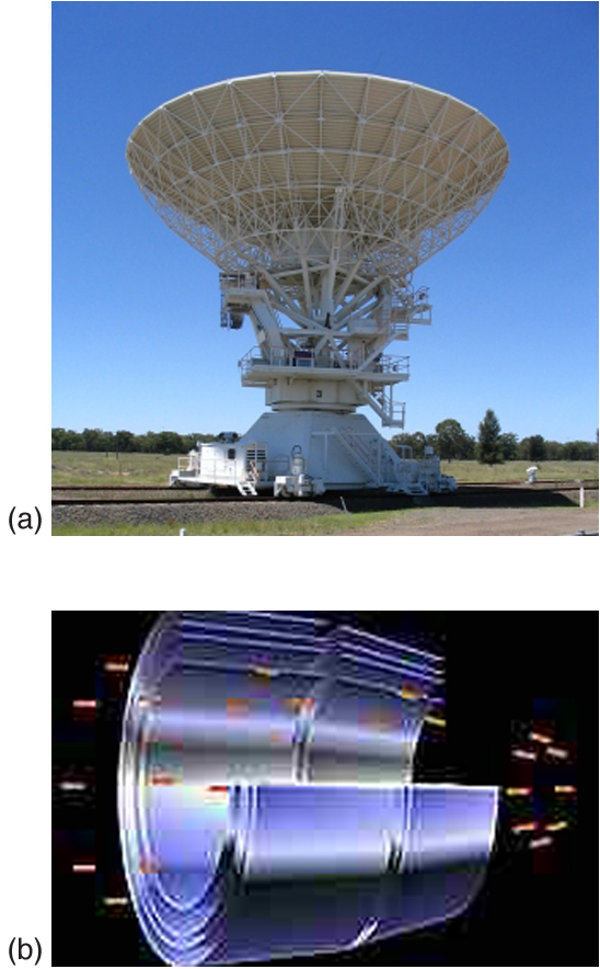
Image a is a photograph one of the antennas from the Australia Telescope Compact Array. Image b is a cutaway diagram showing 4 nested sets of hard x-ray mirrors of the Chandra X-ray observatory.
(a) The Australia Telescope Compact Array at Narrabri (500 km NW of Sydney). (credit: Ian Bailey) (b) The focusing of x rays on the Chandra Observatory, a satellite orbiting earth. X rays ricochet off 4 pairs of mirrors forming a barrelled pathway leading to the focus point. (credit: NASA)

A current exciting development is a collaborative effort involving 17 countries to construct a Square Kilometre Array (SKA) of telescopes capable of covering from 80 MHz to 2 GHz. The initial stage of the project is the construction of the Australian Square Kilometre Array Pathfinder in Western Australia (see [link] ). The project will use cutting-edge technologies such as adaptive optics    in which the lens or mirror is constructed from lots of carefully aligned tiny lenses and mirrors that can be manipulated using computers. A range of rapidly changing distortions can be minimized by deforming or tilting the tiny lenses and mirrors. The use of adaptive optics in vision correction is a current area of research.
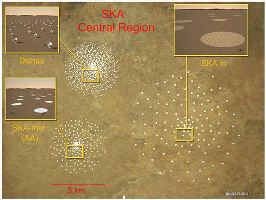
An aerial overview of the central region of the Square Kilometre Array with the five kilometer diameter cores of antennas or dishes is seen. S K A-low array and S K A-mid array, which are phased arrays of simple dipole antennas to cover the frequency range from seventy to two hundred megahertz and two hundred to five hundred megahertz in circular stations, are also displayed.
An artist’s impression of the Australian Square Kilometre Array Pathfinder in Western Australia is displayed. (credit: SPDO, XILOSTUDIOS)

Section summary

  • Simple telescopes can be made with two lenses. They are used for viewing objects at large distances and utilize the entire range of the electromagnetic spectrum.
  • The angular magnification M for a telescope is given by
    M = θ θ = f o f e ,
    where θ is the angle subtended by an object viewed by the unaided eye, θ is the angle subtended by a magnified image, and f o size 12{f rSub { size 8{o} } } {} and f e size 12{f rSub { size 8{e} } } {} are the focal lengths of the objective and the eyepiece.

Conceptual questions

If you want your microscope or telescope to project a real image onto a screen, how would you change the placement of the eyepiece relative to the objective?

Got questions? Get instant answers now!

Problem exercises

Unless otherwise stated, the lens-to-retina distance is 2.00 cm.

What is the angular magnification of a telescope that has a 100 cm focal length objective and a 2.50 cm focal length eyepiece?

40 . 0 size 12{ - {underline {"40" "." 0}} } {}

Got questions? Get instant answers now!

Find the distance between the objective and eyepiece lenses in the telescope in the above problem needed to produce a final image very far from the observer, where vision is most relaxed. Note that a telescope is normally used to view very distant objects.

Got questions? Get instant answers now!

A large reflecting telescope has an objective mirror with a 10 . 0 m size 12{"10" "." 0`m} {} radius of curvature. What angular magnification does it produce when a 3 . 00 m size 12{3 "." "00"`m} {} focal length eyepiece is used?

1 . 67 size 12{ - 1 "." "67"} {}

Got questions? Get instant answers now!

A small telescope has a concave mirror with a 2.00 m radius of curvature for its objective. Its eyepiece is a 4.00 cm focal length lens. (a) What is the telescope’s angular magnification? (b) What angle is subtended by a 25,000 km diameter sunspot? (c) What is the angle of its telescopic image?

Got questions? Get instant answers now!

A 7.5× size 12{7 "." 5 times } {} binocular produces an angular magnification of 7 . 50 size 12{ - 7 "." "50"} {} , acting like a telescope. (Mirrors are used to make the image upright.) If the binoculars have objective lenses with a 75.0 cm focal length, what is the focal length of the eyepiece lenses?

+ 10.0 cm size 12{+"10" "." 0`"cm"} {}

Got questions? Get instant answers now!

Construct Your Own Problem

Consider a telescope of the type used by Galileo, having a convex objective and a concave eyepiece as illustrated in [link] (a). Construct a problem in which you calculate the location and size of the image produced. Among the things to be considered are the focal lengths of the lenses and their relative placements as well as the size and location of the object. Verify that the angular magnification is greater than one. That is, the angle subtended at the eye by the image is greater than the angle subtended by the object.

Got questions? Get instant answers now!

Questions & Answers

material that allows electric current to pass through
Deng Reply
material which don't allow electric current is called
Deng
insulators
Covenant
how to study physic and understand
Ewa Reply
what is conservative force with examples
Moses
what is work
Fredrick Reply
the transfer of energy by a force that causes an object to be displaced; the product of the component of the force in the direction of the displacement and the magnitude of the displacement
AI-Robot
why is it from light to gravity
Esther Reply
difference between model and theory
Esther
Is the ship moving at a constant velocity?
Kamogelo Reply
The full note of modern physics
aluet Reply
introduction to applications of nuclear physics
aluet Reply
the explanation is not in full details
Moses Reply
I need more explanation or all about kinematics
Moses
yes
zephaniah
I need more explanation or all about nuclear physics
aluet
Show that the equal masses particles emarge from collision at right angle by making explicit used of fact that momentum is a vector quantity
Muhammad Reply
yh
Isaac
A wave is described by the function D(x,t)=(1.6cm) sin[(1.2cm^-1(x+6.8cm/st] what are:a.Amplitude b. wavelength c. wave number d. frequency e. period f. velocity of speed.
Majok Reply
what is frontier of physics
Somto Reply
A body is projected upward at an angle 45° 18minutes with the horizontal with an initial speed of 40km per second. In hoe many seconds will the body reach the ground then how far from the point of projection will it strike. At what angle will the horizontal will strike
Gufraan Reply
Suppose hydrogen and oxygen are diffusing through air. A small amount of each is released simultaneously. How much time passes before the hydrogen is 1.00 s ahead of the oxygen? Such differences in arrival times are used as an analytical tool in gas chromatography.
Ezekiel Reply
please explain
Samuel
what's the definition of physics
Mobolaji Reply
what is physics
Nangun Reply
the science concerned with describing the interactions of energy, matter, space, and time; it is especially interested in what fundamental mechanisms underlie every phenomenon
AI-Robot
Practice Key Terms 2

Get Jobilize Job Search Mobile App in your pocket Now!

Get it on Google Play Download on the App Store Now


Source:  OpenStax, College physics. OpenStax CNX. Jul 27, 2015 Download for free at http://legacy.cnx.org/content/col11406/1.9
Google Play and the Google Play logo are trademarks of Google Inc.

Notification Switch

Would you like to follow the 'College physics' conversation and receive update notifications?

Ask