

| << Chapter < Page | Chapter >> Page > |
Thus is called the power factor , which can range from 0 to 1. Power factors near 1 are desirable when designing an efficient motor, for example. At the resonant frequency, .
For the same RLC series circuit having a resistor, a 3.00 mH inductor, a capacitor, and a voltage source with a of 120 V: (a) Calculate the power factor and phase angle for . (b) What is the average power at 50.0 Hz? (c) Find the average power at the circuit’s resonant frequency.
Strategy and Solution for (a)
The power factor at 60.0 Hz is found from
We know from [link] , so that
This small value indicates the voltage and current are significantly out of phase. In fact, the phase angle is
Discussion for (a)
The phase angle is close to , consistent with the fact that the capacitor dominates the circuit at this low frequency (a pure RC circuit has its voltage and current out of phase).
Strategy and Solution for (b)
The average power at 60.0 Hz is
was found to be 0.226 A in [link] . Entering the known values gives
Strategy and Solution for (c)
At the resonant frequency, we know , and was found to be 6.00 A in [link] . Thus,
at resonance (1.30 kHz)
Discussion
Both the current and the power factor are greater at resonance, producing significantly greater power than at higher and lower frequencies.
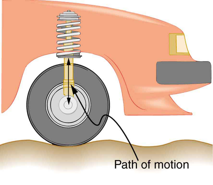
Power delivered to an RLC series AC circuit is dissipated by the resistance alone. The inductor and capacitor have energy input and output but do not dissipate it out of the circuit. Rather they transfer energy back and forth to one another, with the resistor dissipating exactly what the voltage source puts into the circuit. This assumes no significant electromagnetic radiation from the inductor and capacitor, such as radio waves. Such radiation can happen and may even be desired, as we will see in the next chapter on electromagnetic radiation, but it can also be suppressed as is the case in this chapter. The circuit is analogous to the wheel of a car driven over a corrugated road as shown in [link] . The regularly spaced bumps in the road are analogous to the voltage source, driving the wheel up and down. The shock absorber is analogous to the resistance damping and limiting the amplitude of the oscillation. Energy within the system goes back and forth between kinetic (analogous to maximum current, and energy stored in an inductor) and potential energy stored in the car spring (analogous to no current, and energy stored in the electric field of a capacitor). The amplitude of the wheels’ motion is a maximum if the bumps in the road are hit at the resonant frequency.
Notification Switch
Would you like to follow the 'College physics' conversation and receive update notifications?

|
|
|
|
|

|
|

|
|

|
|

|
|

|
|

|
|

|
|

|
|

|
|

|