

| << Chapter < Page | Chapter >> Page > |
The material in this section is correct in theory. We should be able to verify it by making measurements of current and voltage. In fact, some of the devices used to make such measurements are straightforward applications of the principles covered so far and are explored in the next modules. As we shall see, a very basic, even profound, fact results—making a measurement alters the quantity being measured.
Can Kirchhoff’s rules be applied to simple series and parallel circuits or are they restricted for use in more complicated circuits that are not combinations of series and parallel?
Kirchhoff's rules can be applied to any circuit since they are applications to circuits of two conservation laws. Conservation laws are the most broadly applicable principles in physics. It is usually mathematically simpler to use the rules for series and parallel in simpler circuits so we emphasize Kirchhoff’s rules for use in more complicated situations. But the rules for series and parallel can be derived from Kirchhoff’s rules. Moreover, Kirchhoff’s rules can be expanded to devices other than resistors and emfs, such as capacitors, and are one of the basic analysis devices in circuit analysis.
A simple circuit shown below – with two parallel resistors and a voltage source – is implemented in a laboratory experiment with ɛ = 6.00 ± 0.02 V and R 1 = 4.8 ± 0.1 Ω and R 2 = 9.6 ± 0.1 Ω. The values include an allowance for experimental uncertainties as they cannot be measured with perfect certainty. For example if you measure the value for a resistor a few times, you may get slightly different results. Hence values are expressed with some level of uncertainty.
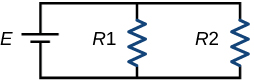
In the laboratory experiment the currents measured in the two resistors are I 1 = 1.27 A and I 2 = 0.62 A respectively. Let us examine these values using Kirchhoff’s laws.
For the two loops,
E - I 1 R 1 = 0 or I 1 = E/R 1
E - I 2 R 2 = 0 or I 2 = E/R 2
Converting the given uncertainties for voltage and resistances into percentages, we get
E = 6.00 V ± 0.33%
R 1 = 4.8 Ω ± 2.08%
R 2 = 9.6 Ω ± 1.04%
We now find the currents for the two loops. While the voltage is divided by the resistance to find the current, uncertainties in voltage and resistance are directly added to find the uncertainty in the current value.
I 1 = (6.00/4.8) ± (0.33%+2.08%)
= 1.25 ± 2.4%
= 1.25 ± 0.03 A
I 2 = (6.00/9.6) ± (0.33%+1.04%)
= 0.63 ± 1.4%
= 0.63 ± 0.01 A
Finally you can check that the two measured values in this case are within the uncertainty ranges found for the currents. However there can also be additional experimental uncertainty in the measurements of currents.
An experiment was set up with the circuit diagram shown. Assume R 1 = 10 Ω, R 2 = R 3 = 5 Ω, r = 0 Ω and E = 6 V.
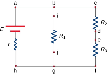
One of the steps to examine the set-up is to test points with the same potential. Which of the following points can be tested?
At which three points should the currents be measured so that Kirchhoff’s junction rule can be directly confirmed?
If the current in the branch with the voltage source is upward and currents in the other two branches are downward, i.e. I a = I i + I c , identify which of the following can be true? Select two answers.
The measurements reveal that the current through R 1 is 0.5 A and R 3 is 0.6 A. Based on your knowledge of Kirchoff’s laws, confirm which of the following statements are true.
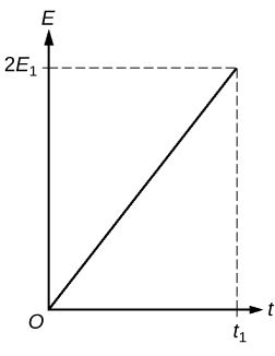
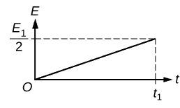
The graph shown in the following figure is the energy dissipated at R 1 as a function of time.
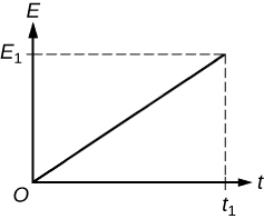
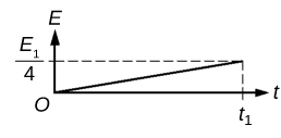
Which of the following shows the graph for energy dissipated at R 2 as a function of time?

Notification Switch
Would you like to follow the 'College physics for ap® courses' conversation and receive update notifications?

|
|
|
|
|

|
|

|
|

|
|

|
|

|
|

|
|
|
|
|

|
|
|
|
|

|