<< Chapter < Page Chapter >> Page >
I 0 Z = I 0 2 R 2 + ( I 0 X L I 0 X C ) 2 = I 0 R 2 + ( X L X C ) 2 . size 12{I rSub { size 8{0} } Z= sqrt {I rSub { size 8{0} rSup { size 8{2} } } R rSup { size 8{2} } + \( I rSub { size 8{0} } X rSub { size 8{L} } - I rSub { size 8{0} } X rSub { size 8{C} } \) rSup { size 8{2} } } =I rSub { size 8{0} } sqrt {R rSup { size 8{2} } + \( X rSub { size 8{L} } - X rSub { size 8{C} } \) rSup { size 8{2} } } } {}

I 0 size 12{I rSub { size 8{0} } } {} cancels to yield an expression for Z :

Z = R 2 + ( X L X C ) 2 , size 12{Z= sqrt {R rSup { size 8{2} } + \( X rSub { size 8{L} } - X rSub { size 8{C} } \) rSup { size 8{2} } } } {}

which is the impedance of an RLC series AC circuit. For circuits without a resistor, take R = 0 ; for those without an inductor, take X L = 0 size 12{X rSub { size 8{L} } =0} {} ; and for those without a capacitor, take X C = 0 size 12{X rSub { size 8{C} } =0} {} .

The figure shows graphs showing the relationships of the voltages in an RLC circuit to the current. It has five graphs on the left and two graphs on the right. The first graph on the right is for current I versus time t. Current is plotted along Y axis and time is along X axis. The curve is a smooth progressive sine wave. The second graph is on the right is for voltage V R versus time t. Voltage V R is plotted along Y axis and time is along X axis. The curve is a smooth progressive sine wave. The third graph is on the right is for voltage V L versus time t. Voltage V L is plotted along Y axis and time is along X axis. The curve is a smooth progressive cosine wave. The fourth graph is on the right is for voltage V C versus time t. Voltage V C is plotted along Y axis and time t is along X axis. The curve is a smooth progressive cosine wave starting from negative Y axis. The fifth graph shows the voltage V verses time t for the R L C circuit. Voltage V is plotted along Y axis and time t is along X axis. The curve is a smooth progressive sine wave starting from a point near to origin on negative X axis. The first and the fifth graphs are again shown on the right and their amplitudes and phases compared. The current graph is shown to have a lesser amplitude.
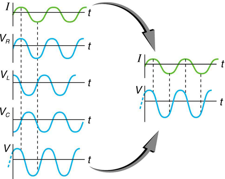
This graph shows the relationships of the voltages in an RLC circuit to the current. The voltages across the circuit elements add to equal the voltage of the source, which is seen to be out of phase with the current.

Calculating impedance and current

An RLC series circuit has a 40.0 Ω resistor, a 3.00 mH inductor, and a 5.00 μF capacitor. (a) Find the circuit’s impedance at 60.0 Hz and 10.0 kHz, noting that these frequencies and the values for L and C are the same as in [link] and [link] . (b) If the voltage source has V rms = 120 V size 12{V rSub { size 8{"rms"} } ="120"`V} {} , what is I rms size 12{I rSub { size 8{"rms"} } } {} at each frequency?

Strategy

For each frequency, we use Z = R 2 + ( X L X C ) 2 size 12{Z= sqrt {R rSup { size 8{2} } + \( X rSub { size 8{L} } - X rSub { size 8{C} } \) rSup { size 8{2} } } } {} to find the impedance and then Ohm’s law to find current. We can take advantage of the results of the previous two examples rather than calculate the reactances again.

Solution for (a)

At 60.0 Hz, the values of the reactances were found in [link] to be X L = 1 . 13 Ω size 12{X rSub { size 8{L} } =1 "." "13" %OMEGA } {} and in [link] to be X C = 531 Ω size 12{X rSub { size 8{C} } ="531 " %OMEGA } {} . Entering these and the given 40.0 Ω for resistance into Z = R 2 + ( X L X C ) 2 size 12{Z= sqrt {R rSup { size 8{2} } + \( X rSub { size 8{L} } - X rSub { size 8{C} } \) rSup { size 8{2} } } } {} yields

Z = R 2 + ( X L X C ) 2 = ( 40 . 0 Ω ) 2 + ( 1 . 13 Ω 531 Ω ) 2 = 531 Ω  at 60 . 0 Hz . alignl { stack { size 12{Z= sqrt {R rSup { size 8{2} } + \( X rSub { size 8{L} } - X rSub { size 8{C} } \) rSup { size 8{2} } } } {} #" "= sqrt { \( "40" "." 0` %OMEGA \) rSup { size 8{2} } + \( 1 "." "13" %OMEGA - "531" %OMEGA \) rSup { size 8{2} } } {} # " "="531" %OMEGA " at 60" "." "0 Hz" {}} } {}

Similarly, at 10.0 kHz, X L = 188 Ω size 12{X rSub { size 8{L} } ="188" %OMEGA } {} and X C = 3 . 18 Ω size 12{X rSub { size 8{C} } =3 "." "18" %OMEGA } {} , so that

Z = ( 40 . 0 Ω ) 2 + ( 188 Ω 3 . 18 Ω ) 2 = 190 Ω  at 10 . 0 kHz. alignl { stack { size 12{Z= sqrt { \( "40" "." 0` %OMEGA \) rSup { size 8{2} } + \( "188" %OMEGA - 3 "." "18" %OMEGA \) rSup { size 8{2} } } } {} #" "="190" %OMEGA " at 10" "." "0 kHz" {} } } {}

Discussion for (a)

In both cases, the result is nearly the same as the largest value, and the impedance is definitely not the sum of the individual values. It is clear that X L size 12{X rSub { size 8{L} } } {} dominates at high frequency and X C size 12{X rSub { size 8{C} } } {} dominates at low frequency.

Solution for (b)

The current I rms size 12{I rSub { size 8{"rms"} } } {} can be found using the AC version of Ohm’s law in Equation I rms = V rms / Z size 12{I rSub { size 8{"rms"} } =V rSub { size 8{"rms"} } /Z} {} :

I rms = V rms Z = 120 V 531 Ω = 0 . 226 A size 12{I rSub { size 8{"rms"} } = { {V rSub { size 8{"rms"} } } over {Z} } = { {"120"" V"} over {"531 " %OMEGA } } =0 "." "226"" A"} {} at 60.0 Hz

Finally, at 10.0 kHz, we find

I rms = V rms Z = 120 V 190 Ω = 0 . 633 A size 12{I rSub { size 8{"rms"} } = { {V rSub { size 8{"rms"} } } over {Z} } = { {"120"" V"} over {"190 " %OMEGA } } =0 "." "633"" A"} {} at 10.0 kHz

Discussion for (a)

The current at 60.0 Hz is the same (to three digits) as found for the capacitor alone in [link] . The capacitor dominates at low frequency. The current at 10.0 kHz is only slightly different from that found for the inductor alone in [link] . The inductor dominates at high frequency.

Got questions? Get instant answers now!

Resonance in RLC Series ac circuits

How does an RLC circuit behave as a function of the frequency of the driving voltage source? Combining Ohm’s law, I rms = V rms / Z size 12{I rSub { size 8{"rms"} } =V rSub { size 8{"rms"} } /Z} {} , and the expression for impedance Z from Z = R 2 + ( X L X C ) 2 size 12{Z= sqrt {R rSup { size 8{2} } + \( X rSub { size 8{L} } - X rSub { size 8{C} } \) rSup { size 8{2} } } } {} gives

I rms = V rms R 2 + ( X L X C ) 2 . size 12{I rSub { size 8{"rms"} } = { {V rSub { size 8{"rms"} } } over { sqrt {R rSup { size 8{2} } + \( X rSub { size 8{L} } - X rSub { size 8{C} } \) rSup { size 8{2} } } } } } {}

The reactances vary with frequency, with X L size 12{X rSub { size 8{L} } } {} large at high frequencies and X C size 12{X rSub { size 8{C} } } {} large at low frequencies, as we have seen in three previous examples. At some intermediate frequency f 0 size 12{f rSub { size 8{0} } } {} , the reactances will be equal and cancel, giving Z = R size 12{Z=R} {} —this is a minimum value for impedance, and a maximum value for I rms size 12{I rSub { size 8{"rms"} } } {} results. We can get an expression for f 0 size 12{f rSub { size 8{0} } } {} by taking

X L = X C . size 12{X rSub { size 8{L} } =X rSub { size 8{C} } } {}

Substituting the definitions of X L size 12{X rSub { size 8{L} } } {} and X C size 12{X rSub { size 8{C} } } {} ,

2 πf 0 L = 1 2 πf 0 C . size 12{2πf rSub { size 8{0} } L= { {1} over {2πf rSub { size 8{0} } C} } } {}

Solving this expression for f 0 size 12{f rSub { size 8{0} } } {} yields

f 0 = 1 LC , size 12{f rSub { size 8{0} } = { {1} over {2π sqrt { ital "LC"} } } } {}

where f 0 size 12{f rSub { size 8{0} } } {} is the resonant frequency    of an RLC series circuit. This is also the natural frequency at which the circuit would oscillate if not driven by the voltage source. At f 0 size 12{f rSub { size 8{0} } } {} , the effects of the inductor and capacitor cancel, so that Z = R size 12{Z=R} {} , and I rms size 12{I rSub { size 8{"rms"} } } {} is a maximum.

Questions & Answers

if three forces F1.f2 .f3 act at a point on a Cartesian plane in the daigram .....so if the question says write down the x and y components ..... I really don't understand
Syamthanda Reply
hey , can you please explain oxidation reaction & redox ?
Boitumelo Reply
hey , can you please explain oxidation reaction and redox ?
Boitumelo
for grade 12 or grade 11?
Sibulele
the value of V1 and V2
Tumelo Reply
advantages of electrons in a circuit
Rethabile Reply
we're do you find electromagnetism past papers
Ntombifuthi
what a normal force
Tholulwazi Reply
it is the force or component of the force that the surface exert on an object incontact with it and which acts perpendicular to the surface
Sihle
what is physics?
Petrus Reply
what is the half reaction of Potassium and chlorine
Anna Reply
how to calculate coefficient of static friction
Lisa Reply
how to calculate static friction
Lisa
How to calculate a current
Tumelo
how to calculate the magnitude of horizontal component of the applied force
Mogano
How to calculate force
Monambi
a structure of a thermocouple used to measure inner temperature
Anna Reply
a fixed gas of a mass is held at standard pressure temperature of 15 degrees Celsius .Calculate the temperature of the gas in Celsius if the pressure is changed to 2×10 to the power 4
Amahle Reply
How is energy being used in bonding?
Raymond Reply
what is acceleration
Syamthanda Reply
a rate of change in velocity of an object whith respect to time
Khuthadzo
how can we find the moment of torque of a circular object
Kidist
Acceleration is a rate of change in velocity.
Justice
t =r×f
Khuthadzo
how to calculate tension by substitution
Precious Reply
hi
Shongi
hi
Leago
use fnet method. how many obects are being calculated ?
Khuthadzo
khuthadzo hii
Hulisani
how to calculate acceleration and tension force
Lungile Reply
you use Fnet equals ma , newtoms second law formula
Masego
please help me with vectors in two dimensions
Mulaudzi Reply
how to calculate normal force
Mulaudzi
Got questions? Join the online conversation and get instant answers!
Jobilize.com Reply
Practice Key Terms 4

Get Jobilize Job Search Mobile App in your pocket Now!

Get it on Google Play Download on the App Store Now


Source:  OpenStax, College physics for ap® courses. OpenStax CNX. Nov 04, 2016 Download for free at https://legacy.cnx.org/content/col11844/1.14
Google Play and the Google Play logo are trademarks of Google Inc.

Notification Switch

Would you like to follow the 'College physics for ap® courses' conversation and receive update notifications?

Ask