<< Chapter < Page Chapter >> Page >
I 0 Z = I 0 2 R 2 + ( I 0 X L I 0 X C ) 2 = I 0 R 2 + ( X L X C ) 2 . size 12{I rSub { size 8{0} } Z= sqrt {I rSub { size 8{0} rSup { size 8{2} } } R rSup { size 8{2} } + \( I rSub { size 8{0} } X rSub { size 8{L} } - I rSub { size 8{0} } X rSub { size 8{C} } \) rSup { size 8{2} } } =I rSub { size 8{0} } sqrt {R rSup { size 8{2} } + \( X rSub { size 8{L} } - X rSub { size 8{C} } \) rSup { size 8{2} } } } {}

I 0 size 12{I rSub { size 8{0} } } {} cancels to yield an expression for Z :

Z = R 2 + ( X L X C ) 2 , size 12{Z= sqrt {R rSup { size 8{2} } + \( X rSub { size 8{L} } - X rSub { size 8{C} } \) rSup { size 8{2} } } } {}

which is the impedance of an RLC series AC circuit. For circuits without a resistor, take R = 0 ; for those without an inductor, take X L = 0 size 12{X rSub { size 8{L} } =0} {} ; and for those without a capacitor, take X C = 0 size 12{X rSub { size 8{C} } =0} {} .

The figure shows graphs showing the relationships of the voltages in an RLC circuit to the current. It has five graphs on the left and two graphs on the right. The first graph on the right is for current I versus time t. Current is plotted along Y axis and time is along X axis. The curve is a smooth progressive sine wave. The second graph is on the right is for voltage V R versus time t. Voltage V R is plotted along Y axis and time is along X axis. The curve is a smooth progressive sine wave. The third graph is on the right is for voltage V L versus time t. Voltage V L is plotted along Y axis and time is along X axis. The curve is a smooth progressive cosine wave. The fourth graph is on the right is for voltage V C versus time t. Voltage V C is plotted along Y axis and time t is along X axis. The curve is a smooth progressive cosine wave starting from negative Y axis. The fifth graph shows the voltage V verses time t for the R L C circuit. Voltage V is plotted along Y axis and time t is along X axis. The curve is a smooth progressive sine wave starting from a point near to origin on negative X axis. The first and the fifth graphs are again shown on the right and their amplitudes and phases compared. The current graph is shown to have a lesser amplitude.
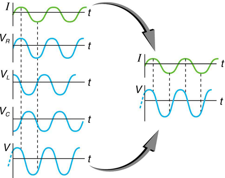
This graph shows the relationships of the voltages in an RLC circuit to the current. The voltages across the circuit elements add to equal the voltage of the source, which is seen to be out of phase with the current.

Calculating impedance and current

An RLC series circuit has a 40.0 Ω resistor, a 3.00 mH inductor, and a 5.00 μF capacitor. (a) Find the circuit’s impedance at 60.0 Hz and 10.0 kHz, noting that these frequencies and the values for L and C are the same as in [link] and [link] . (b) If the voltage source has V rms = 120 V size 12{V rSub { size 8{"rms"} } ="120"`V} {} , what is I rms size 12{I rSub { size 8{"rms"} } } {} at each frequency?

Strategy

For each frequency, we use Z = R 2 + ( X L X C ) 2 size 12{Z= sqrt {R rSup { size 8{2} } + \( X rSub { size 8{L} } - X rSub { size 8{C} } \) rSup { size 8{2} } } } {} to find the impedance and then Ohm’s law to find current. We can take advantage of the results of the previous two examples rather than calculate the reactances again.

Solution for (a)

At 60.0 Hz, the values of the reactances were found in [link] to be X L = 1 . 13 Ω size 12{X rSub { size 8{L} } =1 "." "13" %OMEGA } {} and in [link] to be X C = 531 Ω size 12{X rSub { size 8{C} } ="531 " %OMEGA } {} . Entering these and the given 40.0 Ω for resistance into Z = R 2 + ( X L X C ) 2 size 12{Z= sqrt {R rSup { size 8{2} } + \( X rSub { size 8{L} } - X rSub { size 8{C} } \) rSup { size 8{2} } } } {} yields

Z = R 2 + ( X L X C ) 2 = ( 40 . 0 Ω ) 2 + ( 1 . 13 Ω 531 Ω ) 2 = 531 Ω  at 60 . 0 Hz . alignl { stack { size 12{Z= sqrt {R rSup { size 8{2} } + \( X rSub { size 8{L} } - X rSub { size 8{C} } \) rSup { size 8{2} } } } {} #" "= sqrt { \( "40" "." 0` %OMEGA \) rSup { size 8{2} } + \( 1 "." "13" %OMEGA - "531" %OMEGA \) rSup { size 8{2} } } {} # " "="531" %OMEGA " at 60" "." "0 Hz" {}} } {}

Similarly, at 10.0 kHz, X L = 188 Ω size 12{X rSub { size 8{L} } ="188" %OMEGA } {} and X C = 3 . 18 Ω size 12{X rSub { size 8{C} } =3 "." "18" %OMEGA } {} , so that

Z = ( 40 . 0 Ω ) 2 + ( 188 Ω 3 . 18 Ω ) 2 = 190 Ω  at 10 . 0 kHz. alignl { stack { size 12{Z= sqrt { \( "40" "." 0` %OMEGA \) rSup { size 8{2} } + \( "188" %OMEGA - 3 "." "18" %OMEGA \) rSup { size 8{2} } } } {} #" "="190" %OMEGA " at 10" "." "0 kHz" {} } } {}

Discussion for (a)

In both cases, the result is nearly the same as the largest value, and the impedance is definitely not the sum of the individual values. It is clear that X L size 12{X rSub { size 8{L} } } {} dominates at high frequency and X C size 12{X rSub { size 8{C} } } {} dominates at low frequency.

Solution for (b)

The current I rms size 12{I rSub { size 8{"rms"} } } {} can be found using the AC version of Ohm’s law in Equation I rms = V rms / Z size 12{I rSub { size 8{"rms"} } =V rSub { size 8{"rms"} } /Z} {} :

I rms = V rms Z = 120 V 531 Ω = 0 . 226 A size 12{I rSub { size 8{"rms"} } = { {V rSub { size 8{"rms"} } } over {Z} } = { {"120"" V"} over {"531 " %OMEGA } } =0 "." "226"" A"} {} at 60.0 Hz

Finally, at 10.0 kHz, we find

I rms = V rms Z = 120 V 190 Ω = 0 . 633 A size 12{I rSub { size 8{"rms"} } = { {V rSub { size 8{"rms"} } } over {Z} } = { {"120"" V"} over {"190 " %OMEGA } } =0 "." "633"" A"} {} at 10.0 kHz

Discussion for (a)

The current at 60.0 Hz is the same (to three digits) as found for the capacitor alone in [link] . The capacitor dominates at low frequency. The current at 10.0 kHz is only slightly different from that found for the inductor alone in [link] . The inductor dominates at high frequency.

Got questions? Get instant answers now!

Resonance in RLC Series ac circuits

How does an RLC circuit behave as a function of the frequency of the driving voltage source? Combining Ohm’s law, I rms = V rms / Z size 12{I rSub { size 8{"rms"} } =V rSub { size 8{"rms"} } /Z} {} , and the expression for impedance Z from Z = R 2 + ( X L X C ) 2 size 12{Z= sqrt {R rSup { size 8{2} } + \( X rSub { size 8{L} } - X rSub { size 8{C} } \) rSup { size 8{2} } } } {} gives

I rms = V rms R 2 + ( X L X C ) 2 . size 12{I rSub { size 8{"rms"} } = { {V rSub { size 8{"rms"} } } over { sqrt {R rSup { size 8{2} } + \( X rSub { size 8{L} } - X rSub { size 8{C} } \) rSup { size 8{2} } } } } } {}

The reactances vary with frequency, with X L size 12{X rSub { size 8{L} } } {} large at high frequencies and X C size 12{X rSub { size 8{C} } } {} large at low frequencies, as we have seen in three previous examples. At some intermediate frequency f 0 size 12{f rSub { size 8{0} } } {} , the reactances will be equal and cancel, giving Z = R size 12{Z=R} {} —this is a minimum value for impedance, and a maximum value for I rms size 12{I rSub { size 8{"rms"} } } {} results. We can get an expression for f 0 size 12{f rSub { size 8{0} } } {} by taking

X L = X C . size 12{X rSub { size 8{L} } =X rSub { size 8{C} } } {}

Substituting the definitions of X L size 12{X rSub { size 8{L} } } {} and X C size 12{X rSub { size 8{C} } } {} ,

2 πf 0 L = 1 2 πf 0 C . size 12{2πf rSub { size 8{0} } L= { {1} over {2πf rSub { size 8{0} } C} } } {}

Solving this expression for f 0 size 12{f rSub { size 8{0} } } {} yields

f 0 = 1 LC , size 12{f rSub { size 8{0} } = { {1} over {2π sqrt { ital "LC"} } } } {}

where f 0 size 12{f rSub { size 8{0} } } {} is the resonant frequency    of an RLC series circuit. This is also the natural frequency at which the circuit would oscillate if not driven by the voltage source. At f 0 size 12{f rSub { size 8{0} } } {} , the effects of the inductor and capacitor cancel, so that Z = R size 12{Z=R} {} , and I rms size 12{I rSub { size 8{"rms"} } } {} is a maximum.

Questions & Answers

start new n questions too
Emmaunella Reply
summarize halerambos & holbon
David Reply
the Three stages of Auguste Comte
Clementina Reply
what are agents of socialization
Antonio Reply
sociology of education
Nuhu Reply
definition of sociology of education
Nuhu
definition of sociology of education
Emmaunella
what is culture
Abdulrahim Reply
shared beliefs, values, and practices
AI-Robot
What are the two type of scientific method
ogunniran Reply
I'm willing to join you
Aceng Reply
what are the scientific method of sociology
Man
what is socialization
ogunniran Reply
the process wherein people come to understand societal norms and expectations, to accept society's beliefs, and to be aware of societal values
AI-Robot
scientific method in doing research
ogunniran
defimition of sickness in afica
Anita
Cosmology
ogunniran
Hmmm
ogunniran
list and explain the terms that found in society
REMMY Reply
list and explain the terms that found in society
Mukhtar
what are the agents of socialization
Antonio
Family Peer group Institution
Abdulwajud
I mean the definition
Antonio
ways of perceived deviance indifferent society
Naomi Reply
reasons of joining groups
SAM
to bring development to the nation at large
Hyellafiya
entails of consultative and consensus building from others
Gadama
World first Sociologist?
Abu
What is evolutionary model
Muhammad Reply
Evolution models refer to mathematical and computational representations of the processes involved in biological evolution. These models aim to simulate and understand how species change over time through mechanisms such as natural selection, genetic drift, and mutation. Evolutionary models can be u
faruk
what are the modern trends in religious behaviours
Selekeye Reply
what are social norms
Daniel Reply
shared standards of acceptable behavior by the group or appropriate behavior in a particular institution or those behaviors that are acceptable in a society
Lucius
that is how i understood it
Lucius
examples of societal norms
Diamond
Discuss the characteristics of the research located within positivist and the interpretivist paradigm
Tariro Reply
Got questions? Join the online conversation and get instant answers!
Jobilize.com Reply
Practice Key Terms 4

Get Jobilize Job Search Mobile App in your pocket Now!

Get it on Google Play Download on the App Store Now


Source:  OpenStax, College physics for ap® courses. OpenStax CNX. Nov 04, 2016 Download for free at https://legacy.cnx.org/content/col11844/1.14
Google Play and the Google Play logo are trademarks of Google Inc.

Notification Switch

Would you like to follow the 'College physics for ap® courses' conversation and receive update notifications?

Ask