<< Chapter < Page Chapter >> Page >

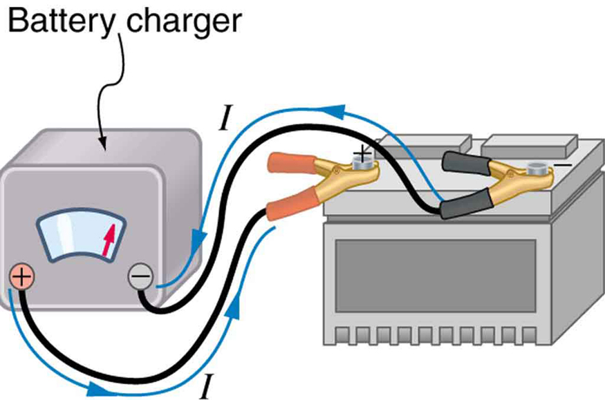
Some batteries can be recharged by passing a current through them in the direction opposite to the current they supply to a resistance. This is done routinely in cars and batteries for small electrical appliances and electronic devices, and is represented pictorially in [link] . The voltage output of the battery charger must be greater than the emf of the battery to reverse current through it. This will cause the terminal voltage of the battery to be greater than the emf, since V = emf Ir size 12{V="emf" - ital "Ir"} {} , and I size 12{I} {} is now negative.

The diagram shows a car battery being charged with cables from a battery charger. The current flows from the positive terminal of the charger to the positive terminal of the battery, through the battery and back out the negative terminal of the battery to the negative terminal of the charger.
A car battery charger reverses the normal direction of current through a battery, reversing its chemical reaction and replenishing its chemical potential.

Multiple voltage sources

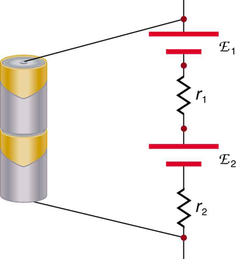
There are two voltage sources when a battery charger is used. Voltage sources connected in series are relatively simple. When voltage sources are in series, their internal resistances add and their emfs add algebraically. (See [link] .) Series connections of voltage sources are common—for example, in flashlights, toys, and other appliances. Usually, the cells are in series in order to produce a larger total emf.

But if the cells oppose one another, such as when one is put into an appliance backward, the total emf is less, since it is the algebraic sum of the individual emfs.

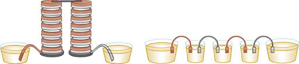
A battery is a multiple connection of voltaic cells, as shown in [link] . The disadvantage of series connections of cells is that their internal resistances add. One of the authors once owned a 1957 MGA that had two 6-V batteries in series, rather than a single 12-V battery. This arrangement produced a large internal resistance that caused him many problems in starting the engine.

This diagram shows two typical batteries in series, with the positive terminal of the first touching the negative terminal of the second. The schematic diagram of the electric current flowing through them is shown as current I passing through the series of two cells of e m f script E sub one and internal resistance r sub one and e m f script E sub two and internal resistance r sub two.
A series connection of two voltage sources. The emfs (each labeled with a script E) and internal resistances add, giving a total emf of emf 1 + emf 2 size 12{"emf" rSub { size 8{1} } +"emf" rSub { size 8{2} } } {} and a total internal resistance of r 1 + r 2 size 12{r rSub { size 8{1} } +r rSub { size 8{2} } } {} .
The left side of the diagram shows a battery that contains a combination of a large number of cells. The right side shows a set of cells combined in series to form a battery.
Batteries are multiple connections of individual cells, as shown in this modern rendition of an old print. Single cells, such as AA or C cells, are commonly called batteries, although this is technically incorrect.

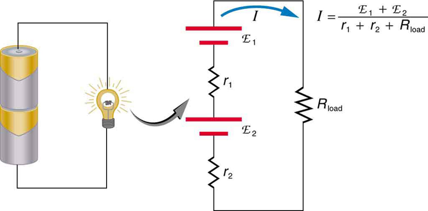
If the series connection of two voltage sources is made into a complete circuit with the emfs in opposition, then a current of magnitude I = emf 1 emf 2 r 1 + r 2 size 12{I= { { left ("emf" rSub { size 8{1} } - "emf" rSub { size 8{2} } right )} over {r rSub { size 8{1} } +r rSub { size 8{2} } } } } {} flows. See [link] , for example, which shows a circuit exactly analogous to the battery charger discussed above. If two voltage sources in series with emfs in the same sense are connected to a load R load size 12{R rSub { size 8{"load"} } } {} , as in [link] , then I = emf 1 + emf 2 r 1 + r 2 + R load size 12{I= { { left ("emf" rSub { size 8{1} } - "emf" rSub { size 8{2} } right )} over {r rSub { size 8{1} } +r rSub { size 8{2} } +R rSub { size 8{"load"} } } } } {} flows.

The diagram shows a closed circuit containing series connection of two cells of e m f script E sub one and internal resistance r sub one and e m f script E sub two and internal resistance r sub two. The positive end of E sub one is connected to the positive end of E sub two.
These two voltage sources are connected in series with their emfs in opposition. Current flows in the direction of the greater emf and is limited to I = emf 1 emf 2 r 1 + r 2 size 12{I= { { left ("emf" rSub { size 8{1} } - "emf" rSub { size 8{2} } right )} over {r rSub { size 8{1} } +r rSub { size 8{2} } } } } {} by the sum of the internal resistances. (Note that each emf is represented by script E in the figure.) A battery charger connected to a battery is an example of such a connection. The charger must have a larger emf than the battery to reverse current through it.
Part a shows a flashlight glowing when connected to two cells joined in series with the positive end of one cell connected to the negative end of the other. Part b shows the schematic circuit for part a. There is a series combination of two cells of e m f script E sub one and internal resistance r sub one and e m f script E sub two and internal resistance r sub two connected to a load resistor R sub load.
This schematic represents a flashlight with two cells (voltage sources) and a single bulb (load resistance) in series. The current that flows is I = emf 1 + emf 2 r 1 + r 2 + R load size 12{I= { { left ("emf" rSub { size 8{1} } - "emf" rSub { size 8{2} } right )} over {r rSub { size 8{1} } +r rSub { size 8{2} } +R rSub { size 8{"load"} } } } } {} . (Note that each emf is represented by script E in the figure.)
Practice Key Terms 4

Get Jobilize Job Search Mobile App in your pocket Now!

Get it on Google Play Download on the App Store Now


Source:  OpenStax, College physics for ap® courses. OpenStax CNX. Nov 04, 2016 Download for free at https://legacy.cnx.org/content/col11844/1.14
Google Play and the Google Play logo are trademarks of Google Inc.

Notification Switch

Would you like to follow the 'College physics for ap® courses' conversation and receive update notifications?

Ask