Explain the differences among the simple thermodynamic processes—isobaric, isochoric, isothermal, and adiabatic.
Calculate total work done in a cyclical thermodynamic process.
The information presented in this section supports the following AP® learning objectives and science practices:
5.B.5.6 The student is able to design an experiment and analyze graphical data in which interpretations of the area under a pressure-volume curve are needed to determine the work done on or by the object or system.
(S.P. 4.2, 5.1)
5.B.7.2 The student is able to create a plot of pressure versus volume for a thermodynamic process from given data.
(S.P. 1.1)
5.B.7.3 The student is able to use a plot of pressure versus volume for a thermodynamic process to make calculations of internal energy changes, heat, or work, based upon conservation of energy principles (i.e., the first law of thermodynamics).
(S.P. 1.1, 1.4, 2.2)
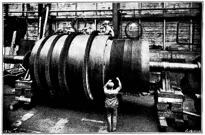
Beginning with the Industrial Revolution, humans have harnessed power through the use of the first law of thermodynamics, before we even understood it completely. This photo, of a steam engine at the Turbinia Works, dates from 1911, a mere 61 years after the first explicit statement of the first law of thermodynamics by Rudolph Clausius. (credit: public domain; author unknown)
One of the most important things we can do with heat transfer is to use it to do work for us. Such a device is called a
heat engine . Car engines and steam turbines that generate electricity are examples of heat engines.
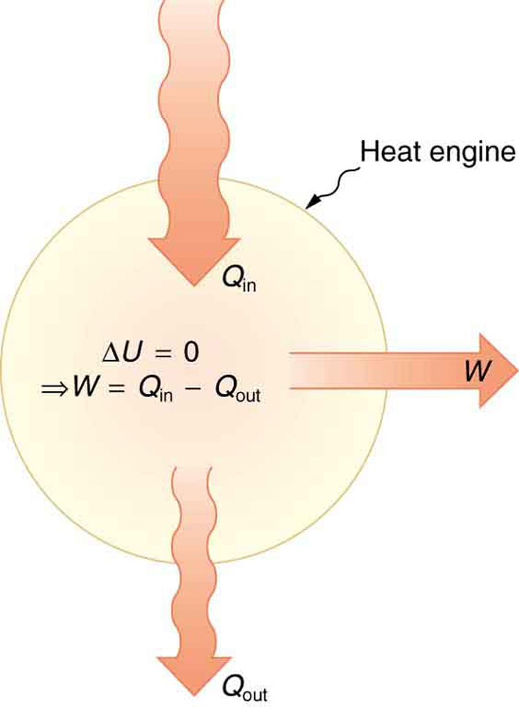
[link] shows schematically how the first law of thermodynamics applies to the typical heat engine.
Schematic representation of a heat engine, governed, of course, by the first law of thermodynamics. It is impossible to devise a system where
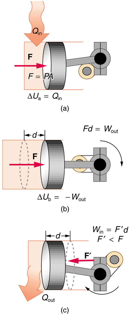
, that is, in which no heat transfer occurs to the environment.(a) Heat transfer to the gas in a cylinder increases the internal energy of the gas, creating higher pressure and temperature. (b) The force exerted on the movable cylinder does work as the gas expands. Gas pressure and temperature decrease when it expands, indicating that the gas's internal energy has been decreased by doing work. (c) Heat transfer to the environment further reduces pressure in the gas so that the piston can be more easily returned to its starting position.
The illustrations above show one of the ways in which heat transfer does work. Fuel combustion produces heat transfer to a gas in a cylinder, increasing the pressure of the gas and thereby the force it exerts on a movable piston. The gas does work on the outside world, as this force moves the piston through some distance. Heat transfer to the gas cylinder results in work being done. To repeat this process, the piston needs to be returned to its starting point. Heat transfer now occurs from the gas to the surroundings so that its pressure decreases, and a force is exerted by the surroundings to push the piston back through some distance. Variations of this process are employed daily in hundreds of millions of heat engines. We will examine heat engines in detail in the next section. In this section, we consider some of the simpler underlying processes on which heat engines are based.