

| << Chapter < Page | Chapter >> Page > |
By the end of this section, you will be able to:
The information presented in this section supports the following AP® learning objectives and science practices:
Electricity has two hazards. A thermal hazard occurs when there is electrical overheating. A shock hazard occurs when electric current passes through a person. Both hazards have already been discussed. Here we will concentrate on systems and devices that prevent electrical hazards.
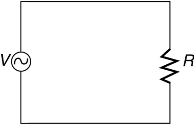
[link] shows the schematic for a simple AC circuit with no safety features. This is not how power is distributed in practice. Modern household and industrial wiring requires the three-wire system , shown schematically in [link] , which has several safety features. First is the familiar circuit breaker (or fuse ) to prevent thermal overload. Second, there is a protective case around the appliance, such as a toaster or refrigerator. The case’s safety feature is that it prevents a person from touching exposed wires and coming into electrical contact with the circuit, helping prevent shocks.
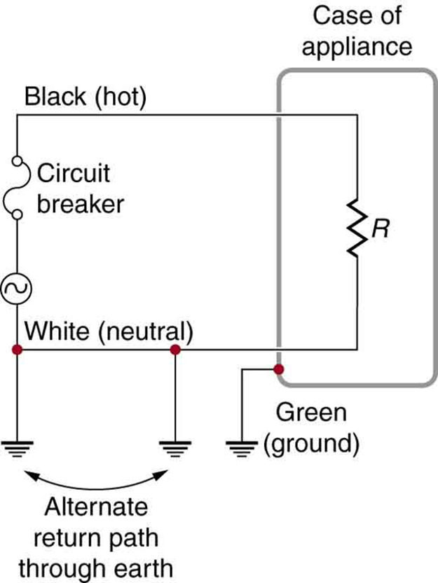
There are three connections to earth or ground (hereafter referred to as “earth/ground”) shown in [link] . Recall that an earth/ground connection is a low-resistance path directly to the earth. The two earth/ground connections on the neutral wire force it to be at zero volts relative to the earth, giving the wire its name. This wire is therefore safe to touch even if its insulation, usually white, is missing. The neutral wire is the return path for the current to follow to complete the circuit. Furthermore, the two earth/ground connections supply an alternative path through the earth, a good conductor, to complete the circuit. The earth/ground connection closest to the power source could be at the generating plant, while the other is at the user’s location. The third earth/ground is to the case of the appliance, through the green earth/ground wire , forcing the case, too, to be at zero volts. The live or hot wire (hereafter referred to as “live/hot”) supplies voltage and current to operate the appliance. [link] shows a more pictorial version of how the three-wire system is connected through a three-prong plug to an appliance.
Notification Switch
Would you like to follow the 'College physics for ap® courses' conversation and receive update notifications?

|
|

|
|

|
|

|
|

|
|

|
|

|
|

|
|

|
|

|
|
|
|