<< Chapter < Page Chapter >> Page >

Learning objectives

By the end of this section, you will be able to:

  • Describe the action of a capacitor and define capacitance.
  • Explain parallel plate capacitors and their capacitances.
  • Discuss the process of increasing the capacitance of a capacitor with a dielectric.
  • Determine capacitance given charge and voltage.

The information presented in this section supports the following AP® learning objectives and science pracitces:

  • 4.E.4.1 The student is able to make predictions about the properties of resistors and/or capacitors when placed in a simple circuit based on the geometry of the circuit element and supported by scientific theories and mathematical relationships. (S.P. 2.2, 6.4)
  • 4.E.4.2 The student is able to design a plan for the collection of data to determine the effect of changing the geometry and/or materials on the resistance or capacitance of a circuit element and relate results to the basic properties of resistors and capacitors. (S.P. 4.1, 4.2)
  • 4.E.4.3 The student is able to analyze data to determine the effect of changing the geometry and/or materials on the resistance or capacitance of a circuit element and relate results to the basic properties of resistors and capacitors. (S.P. 5.1)

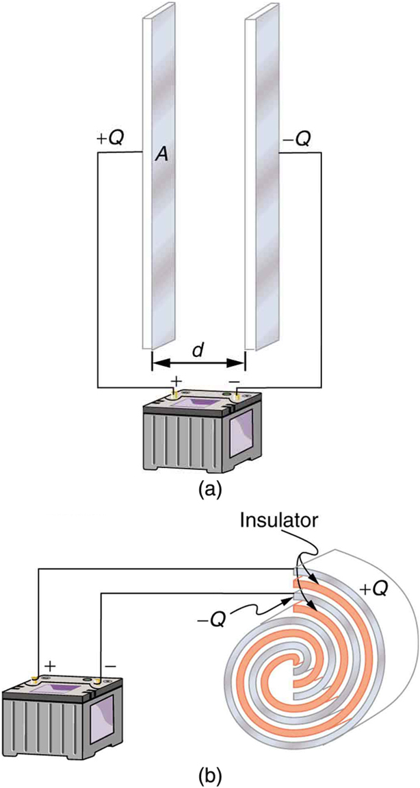
A capacitor    is a device used to store electric charge. Capacitors have applications ranging from filtering static out of radio reception to energy storage in heart defibrillators. Typically, commercial capacitors have two conducting parts close to one another, but not touching, such as those in [link] . (Most of the time an insulator is used between the two plates to provide separation—see the discussion on dielectrics below.) When battery terminals are connected to an initially uncharged capacitor, equal amounts of positive and negative charge, + Q size 12{Q} {} and Q size 12{Q} {} , are separated into its two plates. The capacitor remains neutral overall, but we refer to it as storing a charge Q size 12{Q} {} in this circumstance.

Capacitor

A capacitor is a device used to store electric charge.

Part a of the figure shows a charged parallel plate capacitor and part b of the figure shows a charged rolled capacitor. In the parallel plate capacitor, two rectangular plates are kept vertically facing each other separated by a distance d. These two plates are the conducting parts of the capacitor. One plate is connected to the positive terminal of the battery, and the other is connected to the negative terminal of the battery. One plate has a positive charge, plus Q, and the other plate has a negative charge, negative Q. The rolled capacitor has conducting parts in the form of a spiral coil. Between the two conducting parts is insulating material, also in the form of a coil. The conducting and insulating materials of the capacitor are rolled together to form a spiral. The outer conducting coil is connected to the positive terminal of the battery, and the inner coil is connected to the negative terminal of the battery.
Both capacitors shown here were initially uncharged before being connected to a battery. They now have separated charges of + Q size 12{Q} {} and Q size 12{Q} {} on their two halves. (a) A parallel plate capacitor. (b) A rolled capacitor with an insulating material between its two conducting sheets.

The amount of charge Q size 12{Q} {} a capacitor can store depends on two major factors—the voltage applied and the capacitor’s physical characteristics, such as its size.

The amount of charge Q size 12{Q} {} A capacitor can store

The amount of charge Q size 12{Q} {} a capacitor can store depends on two major factors—the voltage applied and the capacitor’s physical characteristics, such as its size.

A system composed of two identical, parallel conducting plates separated by a distance, as in [link] , is called a parallel plate capacitor    . It is easy to see the relationship between the voltage and the stored charge for a parallel plate capacitor, as shown in [link] . Each electric field line starts on an individual positive charge and ends on a negative one, so that there will be more field lines if there is more charge. (Drawing a single field line per charge is a convenience, only. We can draw many field lines for each charge, but the total number is proportional to the number of charges.) The electric field strength is, thus, directly proportional to Q size 12{Q} {} .

Practice Key Terms 6

Get Jobilize Job Search Mobile App in your pocket Now!

Get it on Google Play Download on the App Store Now


Source:  OpenStax, College physics for ap® courses. OpenStax CNX. Nov 04, 2016 Download for free at https://legacy.cnx.org/content/col11844/1.14
Google Play and the Google Play logo are trademarks of Google Inc.

Notification Switch

Would you like to follow the 'College physics for ap® courses' conversation and receive update notifications?

Ask