

| << Chapter < Page | Chapter >> Page > |
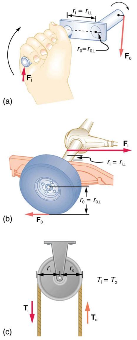
A crank is a lever that can be rotated about its pivot, as shown in [link] . Such a machine may not look like a lever, but the physics of its actions remain the same. The MA for a crank is simply the ratio of the radii . Wheels and gears have this simple expression for their MAs too. The MA can be greater than 1, as it is for the crank, or less than 1, as it is for the simplified car axle driving the wheels, as shown. If the axle's radius is and the wheel's radius is , then and the axle would have to exert a force of on the wheel to enable it to exert a force of on the ground.
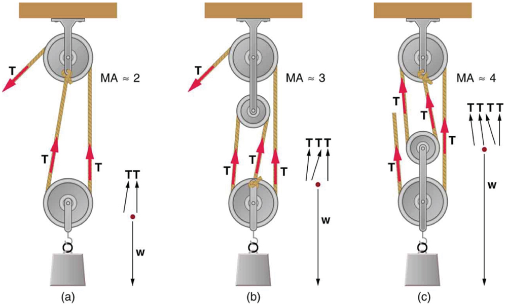
An ordinary pulley has an MA of 1; it only changes the direction of the force and not its magnitude. Combinations of pulleys, such as those illustrated in [link] , are used to multiply force. If the pulleys are friction-free, then the force output is approximately an integral multiple of the tension in the cable. The number of cables pulling directly upward on the system of interest, as illustrated in the figures given below, is approximately the MA of the pulley system. Since each attachment applies an external force in approximately the same direction as the others, they add, producing a total force that is nearly an integral multiple of the input force .
Scissors are like a double-lever system. Which of the simple machines in [link] and [link] is most analogous to scissors?
Suppose you pull a nail at a constant rate using a nail puller as shown in [link] . Is the nail puller in equilibrium? What if you pull the nail with some acceleration – is the nail puller in equilibrium then? In which case is the force applied to the nail puller larger and why?
Notification Switch
Would you like to follow the 'College physics for ap® courses' conversation and receive update notifications?

|
|
|
|
|

|
|

|
|

|
|

|
|

|
|

|
|

|
|

|
|

|
|

|