In a circuit, a parallel combination of two 20-Ω and one 10-Ω resistors is connected in series with a 4-Ω resistor. The source voltage is 36 V.
Find the resistor(s) with the maximum current.
Find the resistor(s) with the maximum voltage drop.
Find the power dissipated in each resistor and hence the total power dissipated in all the resistors. Also find the power output of the source. Are they equal or not? Justify your answer.
Will the answers for questions (a) and (b) differ if a 3 Ω resistor is added in series to the 4 Ω resistor? If yes, repeat the question(s) for the new resistor combination.
If the values of all the resistors and the source voltage are doubled, what will be the effect on the current?
(a) 4-Ω resistor; (b) combination of 20-Ω, 20-Ω, and 10-Ω resistors; (c) 20 W in each 20-Ω resistor, 40 W in 10-Ω resistor, 64 W in 4-Ω resistor, total 144W total in resistors, output power is 144 W, yes they are equal (law of conservation of energy); (d) 4 Ω and 3 Ω for part (a) and no change for part (b); (e) no effect, it will remain the same.
The total resistance of an electrical circuit with resistors wired in a series is the sum of the individual resistances:
Each resistor in a series circuit has the same amount of current flowing through it.
The voltage drop, or power dissipation, across each individual resistor in a series is different, and their combined total adds up to the power source input.
The total resistance of an electrical circuit with resistors wired in parallel is less than the lowest resistance of any of the components and can be determined using the formula:
Each resistor in a parallel circuit has the same full voltage of the source applied to it.
The current flowing through each resistor in a parallel circuit is different, depending on the resistance.
If a more complex connection of resistors is a combination of series and parallel, it can be reduced to a single equivalent resistance by identifying its various parts as series or parallel, reducing each to its equivalent, and continuing until a single resistance is eventually reached.
Conceptual questions
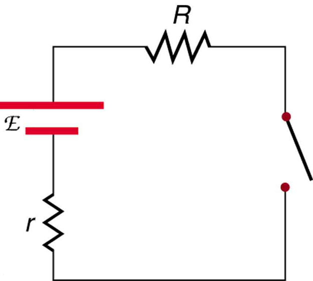
A switch has a variable resistance that is nearly zero when closed and extremely large when open, and it is placed in series with the device it controls. Explain the effect the switch in
[link] has on current when open and when closed.
A switch is ordinarily in series with a resistance and voltage source. Ideally, the switch has nearly zero resistance when closed but has an extremely large resistance when open. (Note that in this diagram, the script E represents the voltage (or electromotive force) of the battery.)
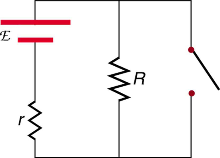
A student in a physics lab mistakenly wired a light bulb, battery, and switch as shown in
[link] . Explain why the bulb is on when the switch is open, and off when the switch is closed. (Do not try this—it is hard on the battery!)
A wiring mistake put this switch in parallel with the device represented by
. (Note that in this diagram, the script E represents the voltage (or electromotive force) of the battery.)