<< Chapter < Page Chapter >> Page >
emf = 2 Bℓ w 2 ω sin ωt = ( w ) sin ωt . size 12{"emf"=2Bℓ { {w} over {2} } ω"sin"ωt= \( ℓw \) Bω"sin"ωt} {}

Noting that the area of the loop is A = w size 12{A=ℓw} {} , and allowing for N size 12{N} {} loops, we find that

emf = NAB ω sin ωt size 12{"emf"= ital "NAB"ω"sin"ωt} {}

is the emf induced in a generator coil    of N size 12{N} {} turns and area A size 12{A} {} rotating at a constant angular velocity ω in a uniform magnetic field B size 12{B} {} . This can also be expressed as

emf = emf 0 sin ωt , size 12{"emf"="emf" rSub { size 8{0} } "sin"ωt} {}

where

emf 0 = NAB ω size 12{"emf" rSub { size 8{0} } = ital "NAB"ω} {}

is the maximum (peak) emf . Note that the frequency of the oscillation is f = ω / size 12{f=ω/2π} {} , and the period is T = 1 / f = / ω size 12{T=1/f=2π/ω} {} . [link] shows a graph of emf as a function of time, and it now seems reasonable that AC voltage is sinusoidal.
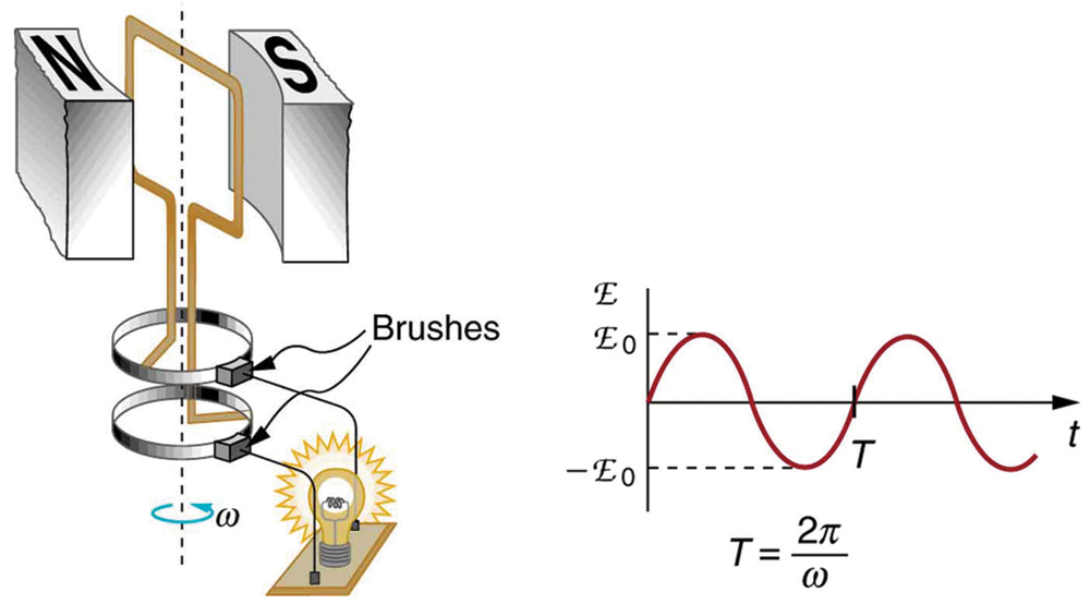
The first part of the figure shows a schematic diagram of a single coil electric generator. It consists of a rotating rectangular loop placed between the two poles of a permanent magnet shown as two rectangular blocks curved on side facing the loop. The magnetic field B is shown pointing from the North to the South Pole. The two ends of this loop are connected to the two small rings. The two conducting carbon brushes are kept pressed separately on both the rings. The loop is rotated in the field with an angular velocity omega. Outer ends of the two brushes are connected to an electric bulb which is shown to glow brightly. The second part of the figure shows the graph for e m f generated E as a function of time t. The e m f is along the Y axis and the time t is along the X axis. The graph is a progressive sine wave with a time period T. The crest maxima are at E zero and trough minima are at negative E zero.
The emf of a generator is sent to a light bulb with the system of rings and brushes shown. The graph gives the emf of the generator as a function of time. emf 0 size 12{"emf" rSub { size 8{0} } } {} is the peak emf. The period is T = 1 / f = / ω size 12{T=1/f=2π/ω} {} , where f size 12{f} {} is the frequency. Note that the script E stands for emf.

The fact that the peak emf, emf 0 = NAB ω size 12{"emf" rSub { size 8{0} } = ital "NAB"ω} {} , makes good sense. The greater the number of coils, the larger their area, and the stronger the field, the greater the output voltage. It is interesting that the faster the generator is spun (greater ω size 12{ω} {} ), the greater the emf. This is noticeable on bicycle generators—at least the cheaper varieties. One of the authors as a juvenile found it amusing to ride his bicycle fast enough to burn out his lights, until he had to ride home lightless one dark night.

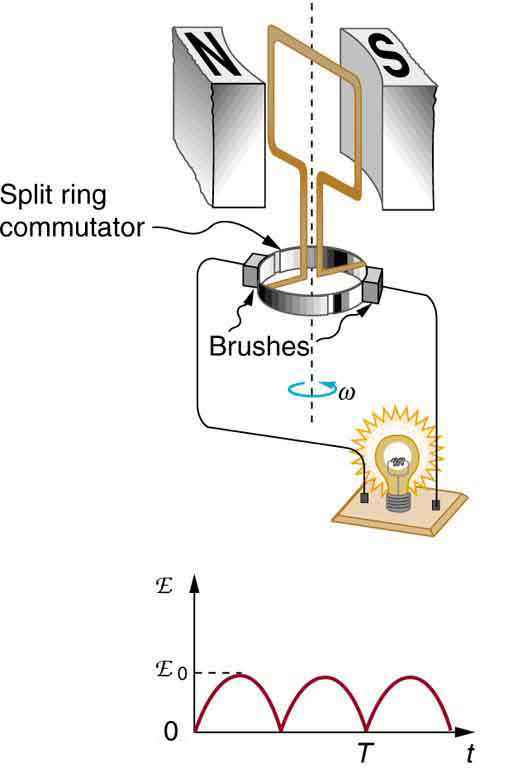
[link] shows a scheme by which a generator can be made to produce pulsed DC. More elaborate arrangements of multiple coils and split rings can produce smoother DC, although electronic rather than mechanical means are usually used to make ripple-free DC.

The first part of the figure shows a schematic diagram of a single coil D C electric generator. It consists of a rotating rectangular loop placed between the two poles of a permanent magnet shown as two rectangular blocks curved on side facing the loop. The magnetic field B is shown pointing from the North to the South Pole. The two ends of this loop are connected to the two sides of a split ring. The two conducting carbon brushes are kept pressed separately on both sides of the split rings. The loop is rotated in the field with an angular velocity w. Outer ends of the two brushes are connected to an electric bulb which is shown to glow brightly. The second part of the figure shows the graph for e m f generated as a function of time. The e m f is along the Y axis and the time t is along the X axis. The graph is a progressive and rectified sine wave with a time period T. The sine wave has only positive pulses. The crest maxima are at E zero.
Split rings, called commutators, produce a pulsed DC emf output in this configuration.

Calculating the maximum emf of a generator

Calculate the maximum emf, emf 0 size 12{"emf" rSub { size 8{0} } } {} , of the generator that was the subject of [link] .

Strategy

Once ω size 12{ω} {} , the angular velocity, is determined, emf 0 = NAB ω size 12{"emf" rSub { size 8{0} } = ital "NAB"ω} {} can be used to find emf 0 size 12{"emf" rSub { size 8{0} } } {} . All other quantities are known.

Solution

Angular velocity is defined to be the change in angle per unit time:

ω = Δ θ Δ t . size 12{ω= { {Δθ} over {Δt} } } {}

One-fourth of a revolution is π/2 size 12{l} {} radians, and the time is 0.0150 s; thus,

ω = π / 2 rad 0.0150 s = 104 . 7 rad/s .

104.7 rad/s is exactly 1000 rpm. We substitute this value for ω size 12{ω} {} and the information from the previous example into emf 0 = NAB ω size 12{"emf" rSub { size 8{0} } = ital "NAB"ω} {} , yielding

emf 0 = NAB ω = 200 ( 7 . 85 × 10 3 m 2 ) ( 1 . 25 T ) ( 104 . 7 rad/s ) = 206 V . alignl { stack { size 12{"emf" rSub { size 8{0} } = ital "NAB"ω} {} #" "="200" \( 7 "." "85" times "10" rSup { size 8{ - 3} } " m" rSup { size 8{2} } \) \( 1 "." "25"" T" \) \( "104" "." 7" rad/s" \) {} # " "="206"" V" {}} } {}

Discussion

The maximum emf is greater than the average emf of 131 V found in the previous example, as it should be.

Got questions? Get instant answers now!

In real life, electric generators look a lot different than the figures in this section, but the principles are the same. The source of mechanical energy that turns the coil can be falling water (hydropower), steam produced by the burning of fossil fuels, or the kinetic energy of wind. [link] shows a cutaway view of a steam turbine; steam moves over the blades connected to the shaft, which rotates the coil within the generator.

Photograph of a steam turbine connected to a generator.
Steam turbine/generator. The steam produced by burning coal impacts the turbine blades, turning the shaft which is connected to the generator. (credit: Nabonaco, Wikimedia Commons)

Generators illustrated in this section look very much like the motors illustrated previously. This is not coincidental. In fact, a motor becomes a generator when its shaft rotates. Certain early automobiles used their starter motor as a generator. In Back Emf , we shall further explore the action of a motor as a generator.

Questions & Answers

if three forces F1.f2 .f3 act at a point on a Cartesian plane in the daigram .....so if the question says write down the x and y components ..... I really don't understand
Syamthanda Reply
hey , can you please explain oxidation reaction & redox ?
Boitumelo Reply
hey , can you please explain oxidation reaction and redox ?
Boitumelo
for grade 12 or grade 11?
Sibulele
the value of V1 and V2
Tumelo Reply
advantages of electrons in a circuit
Rethabile Reply
we're do you find electromagnetism past papers
Ntombifuthi
what a normal force
Tholulwazi Reply
it is the force or component of the force that the surface exert on an object incontact with it and which acts perpendicular to the surface
Sihle
what is physics?
Petrus Reply
what is the half reaction of Potassium and chlorine
Anna Reply
how to calculate coefficient of static friction
Lisa Reply
how to calculate static friction
Lisa
How to calculate a current
Tumelo
how to calculate the magnitude of horizontal component of the applied force
Mogano
How to calculate force
Monambi
a structure of a thermocouple used to measure inner temperature
Anna Reply
a fixed gas of a mass is held at standard pressure temperature of 15 degrees Celsius .Calculate the temperature of the gas in Celsius if the pressure is changed to 2×10 to the power 4
Amahle Reply
How is energy being used in bonding?
Raymond Reply
what is acceleration
Syamthanda Reply
a rate of change in velocity of an object whith respect to time
Khuthadzo
how can we find the moment of torque of a circular object
Kidist
Acceleration is a rate of change in velocity.
Justice
t =r×f
Khuthadzo
how to calculate tension by substitution
Precious Reply
hi
Shongi
hi
Leago
use fnet method. how many obects are being calculated ?
Khuthadzo
khuthadzo hii
Hulisani
how to calculate acceleration and tension force
Lungile Reply
you use Fnet equals ma , newtoms second law formula
Masego
please help me with vectors in two dimensions
Mulaudzi Reply
how to calculate normal force
Mulaudzi
Got questions? Join the online conversation and get instant answers!
Jobilize.com Reply
Practice Key Terms 3

Get Jobilize Job Search Mobile App in your pocket Now!

Get it on Google Play Download on the App Store Now


Source:  OpenStax, College physics. OpenStax CNX. Jul 27, 2015 Download for free at http://legacy.cnx.org/content/col11406/1.9
Google Play and the Google Play logo are trademarks of Google Inc.

Notification Switch

Would you like to follow the 'College physics' conversation and receive update notifications?

Ask