Although the DFT filterbanks are widely used, there is a problem
with aliasing in the decimated channels. At first glance, onemight think that this is an insurmountable problem and must
simply be accepted. Clearly, with FIR filters and maximaldecimation, aliasing will occur. However, a simple example will
show that it is possible to
exactly cancel out
aliasing under certain conditions!!!
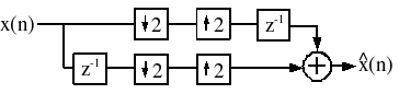
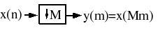
Consider the following trivial filterbank system, with two
channels. (
[link] )
Note
with no error whatsoever, although clearly aliasing
occurs in both channels! Note that the overall data rate isstill the Nyquist rate, so there are clearly enough degrees of
freedom available to reconstruct the data, if the filterbank isdesigned carefully. However, this isn't splitting the data into
separate frequency bands, so one questions whether somethingother than this trivial example could work.
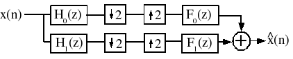
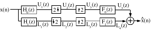
Let's consider a general two-channel filterbank, and try to
determine conditions under which aliasing can be cancelled, andthe signal can be reconstructed perfectly (
[link] ).
Let's derive
, using z-transforms, in terms of the components of
this system. Recall (
[link] ) is equivalent to
and note that (
[link] ) is equivalent to
and (
[link] ) is equivalent to
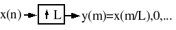
is derived in the downsampler as follows:
Let
and
, then
Now
so
Armed with these results, let's determine
. (
[link] )
Note
and
Finally then,
Note that the
corresponds to the aliasing terms!
There are four things we would like to have:
No aliasing distortion
No phase distortion (overall linear phase → simple time delay)
No amplitude distortion
FIR filters
No aliasing distortion
By insisting that
, the
component of
can be removed, and all aliasing will be eliminated!
There may be many choices for
,
,
,
that eliminate aliasing, but most research has focused on the choice
We will consider only this choice in the following discussion.
Phase distortion
The transfer function of the
filter bank, with aliasing cancelled, becomes
, which with the above choice becomes
. We would like
to correspond to a linear-phase filter to eliminate
phase distortion: Call
Note that
Note that
, and that if
is a linear-phase filter,
is also (perhaps of the opposite symmetry). Also note
that the sum of two linear-phase filters of the same symmetry(
i.e. , length of
must be
odd ) is also linear
phase, so if
is an odd-length linear-phase filter, there will be no
phase distortion. Also note that
means
, when
is even.
If we choose
and
to be linear phase,
will also be linear phase. Thus by choosing
and
to be FIR linear phase, we eliminate phase distortion
and get FIR filters as well (condition 4).
Amplitude distortion
Assuming aliasing cancellation
and elimination of phase distortion, we might also desire noamplitude distortion (
). All of these conditions require
where
is some constant and
is a linear phase delay.
for
. It can be shown by considering that the following
can be satisfied!
Thus we require
Any factorization of a
of this form,
can lead to a Perfect Reconstruction filter bank of
the form
[This result is attributed to Vetterli.] A well-known specialcase (Smith and Barnwell)
Design techniques exist for optimally choosing the coefficients
of these filters, under all of these constraints.
Quadrature mirror filters
for real-valued filters. The frequency response is "mirrored" around
. This choice leads to
: it can be shown that this can be a perfect
reconstruction system only if
which isn't a very flexible choice of filters, and not a very
good lowpass! The Smith and Barnwell approach is more commonlyused today.