

| << Chapter < Page | Chapter >> Page > |
As is common for many 1960’s and 70’s Lotus cars, the front brake calipers are Girling 14LF. These were widely used over this period by domestic manufacturers such as Ford and Triumph. A schematic of the caliper and brake assembly is shown in [link] .

The brake pads are removed by releasing the clips from the retaining pins. The pins are then slid out of the caliper assembly, at which point the pads are removed out the back of each assembly. Using a screwdriver, the old piston boots are removed along with their retaining clips ( [link] ).

The pistons can then be removed by connecting the brake caliper to a compressed air source. Placing the caliper assembly into a bench vice and putting an old glove or towel between the pistons, the air is introduced into the caliper. Unless the piston is rusted in place, one or both should be released from their respective barrels.
Unfortunately, in many cases only one of the pistons is removed. If this occurs, the two halves of the caliper assembly must be separated. It is important not to loose the rubber O-ring that is positioned between the caliper halves, since this is not included in most rebuild kits. The half with the piston in is then subjected to air pressure, while the hole that connects the two halves (for brake fluid passage) is covered by a glove or similar. In the present case this resulted in the piston being only partially removed from the caliper assembly, and additional force was applied using vice grips. Due to difficulties in removing the pistons from the caliper assembly, the outer face (barrel) of the pistons was damaged ( [link] ). Given that a seal between piston and the caliper assembly is required, it was decided that it would be easier to replace the pistons.

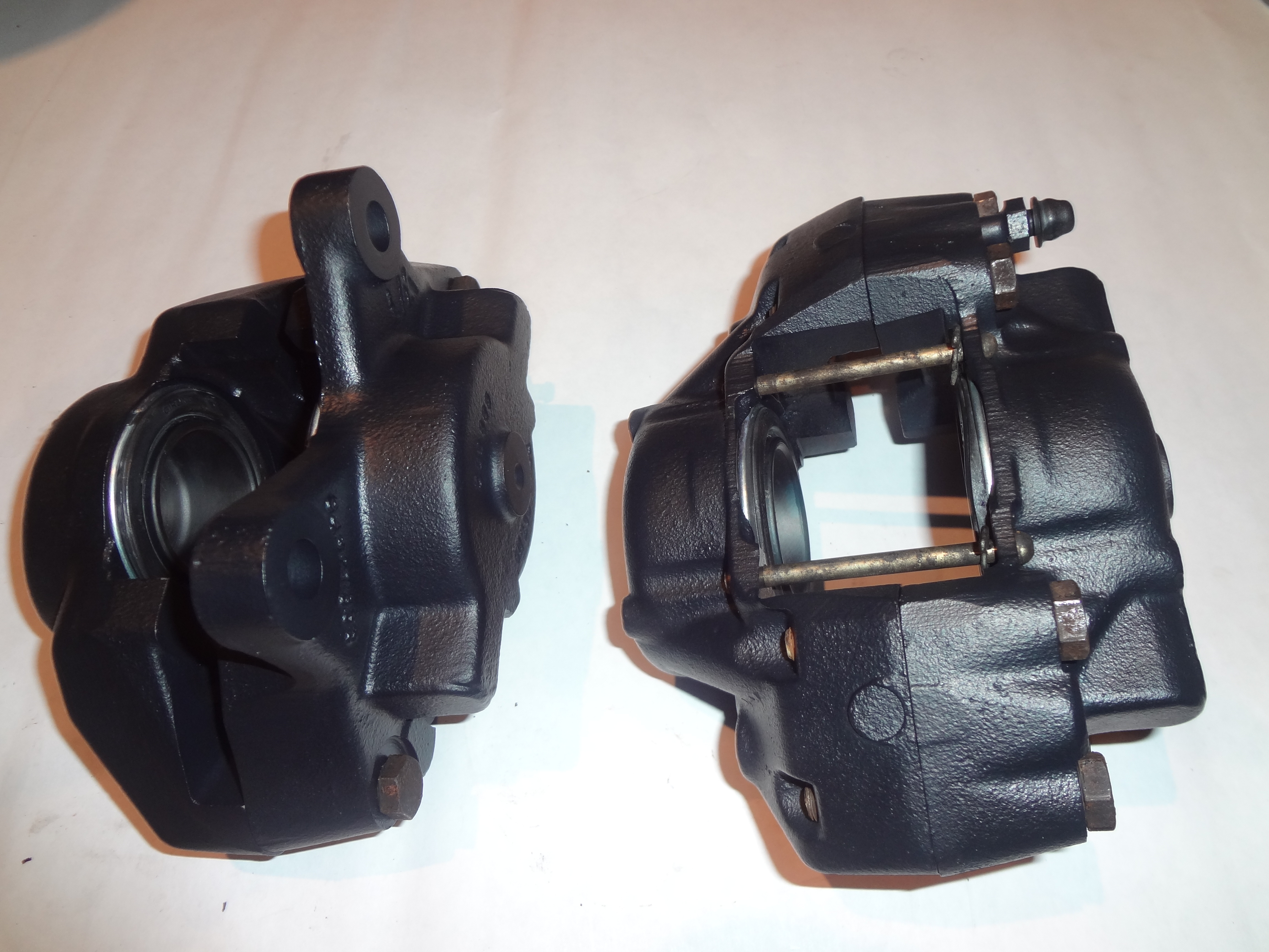
Finally, the rubber seals inside the caliper barrels are removed using a sharp point or a small screwdriver. The two halves of the caliper assembly ( [link] ) are ready for cleaning. The caliper bodies were Teflon ® coated by PolyDyne Performance Coatings. The coating was chosen to allow for the ease of cleaning and removal of brake dust that ordinarily builds up on any suspension components.

The calipers were rebuilt using a TRW rebuild (SP2697) kit from Moss Motors. The rebuild kit consists of 4 piston boots, 4 rubber seals, 4 retaining clips, and 2 rubber dust caps ( [link] and [link] ). One part that does not come in the kit and therefore has to be reused is the rubber washer that seals between the two halves of the caliper. This must be retained from the original; however, all other seals are disposable.


The first task is to install the rubber seal ( [link] A) inside the caliper. The ring is fed into the groove inside the barrel of the caliper, taking care not to damage or twist it ( [link] ). One piston is then installed into each of the caliper halves. It is important to push the piston in straight. In order to ease the piston in, the rubber seal and caliper barrel are greased. A small amount of silicone vacuum grease is suitable, although if none is available, a light rub with break fluid will also work. Once the pistons are fully pressed into the caliper, the piston boot ( [link] B) is stretched over the piston and fitted to the caliper with the retaining clips ( [link] C). The final result is shown in [link] .


Before the two caliper halves are joined, it is important not to forget the rubber washer that seals the fluid passage between the two halves of the caliper ( [link] ). With this in place the two halves are bolted together ( [link] ).


Since brake pads will not be installed until the calipers are fitted to the upright/hub/disk combination, the pad retaining pins and clips are fitted to ensure they do not get lost ( [link] ). A view of the finished calipers is shown in [link] , including the rubber dust caps in place over the bleed screws.

Notification Switch
Would you like to follow the 'Lotus seven s4 (type 60): design, restoration, and maintenance' conversation and receive update notifications?

|
|

|
|

|
|

|
|

|
|

|
|

|
|
|
|
|

|
|

|