

| << Chapter < Page | Chapter >> Page > |
Use the green jumper wires to connect the other side of your switches to GND (the blue bus). Yes, the switch pack is upside down . This is an intentional design decision that has to do with the pull-up configuration of the MSP430 Launchpad Hardware. With the switch pack upside down, flipping the switch "up" will register a "1" and flipping them "down" will register a "0" like you would expect. See the explanation below for more information, or just take it on faith that it works this way.
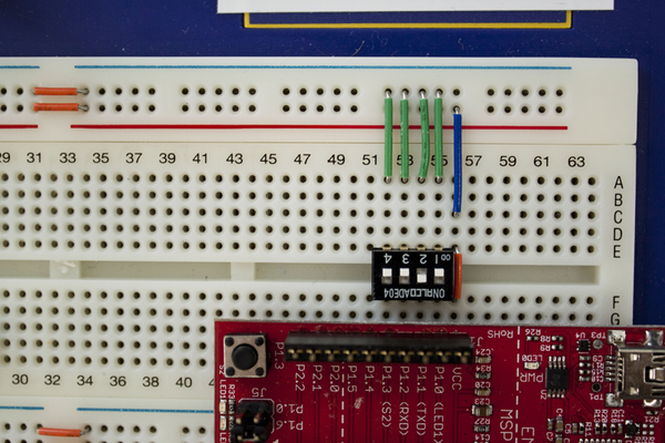
You may notice that turning the switch on connects it to GND, but turning it off connects it to nothing! This can be really bad in a circuit- the values read from the GPIO pins will be essentially random! Ideally, you would want your switches to be "1" when up and "0" when down. To accomplish this, you can either use more expensive dual pole switches that switch between two connections instead of closing or breaking just one, or use what's called a pull up (or pull down) resistor. This is a resistor of large resistance connected to the rail you want the switch to read when it is open. The GPIO sees most of the connected voltage when the switch is on (and in digital applications most is enough), but sees the other rail when the switch is open.
"But I see no resistors in the picture"-- you're right! The MSP430 has pull up resistors built in- we just have to enable them when we configure the GPIO pins. You'll learn more about that in part II of the lab.
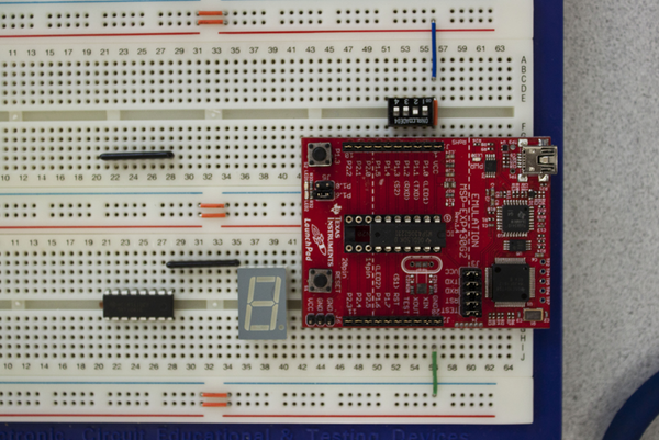
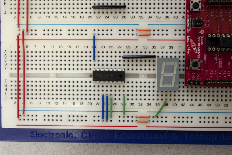
The BCD decoder is an active piece of circuitry, so it needs a power connection to work properly. Connect Vcc to pin 16 (lower A-E column 21) and GND to pin 8 (lower F-J column 28) .
The display also needs a common connection to ground (since it is common cathode type). Connect pin 3 (lower F-J column 38) to GND. The display is just a package of individual LED's in parallel connected to one common ground point.
Lastly, there are some options (dealing with latching and enabling) on the decoder we want to permanently set in our circuit. Connect Vcc to pins 3 and 4 (lower F-J columns 23 and 24) and GND to pin 5 (lower F-J column 25).
Notification Switch
Would you like to follow the 'Intro to computational engineering: elec 220 labs' conversation and receive update notifications?

|
|

|
|

|
|

|
|
|
|

|
|

|
|
|
|
|

|
|

|