<< Chapter < Page Chapter >> Page >
This experiments describes the whole spectrum of active and passive components. The continuity test of these components and their I-V charateristic is described.

Experiment no -1

Name of Experiment :-

Testing of active&passive component with the help of C.R.O and digital multimeter

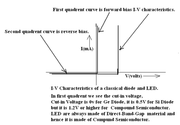
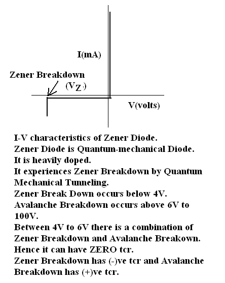
Aim :- To study the function of digital multimeter&C.R.O&testing various components like passive and active components such as resistance, capacitance , inductance, classical diodes, zener diodes, photodiode, Light Emitting Diodes, BJT, JFET and MOSFET.

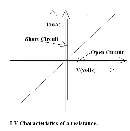
Theory :-In component testing process, we test the continuity and the I-V characteristics of various component like resistor, capacitor, diode and transistors.

Wires and Connectors: we use the following wires:

  1. Single Strand wire of SWG 22 or SWG23. SWG22 is preferred because it snugly fits the solder-less, spring loaded contact points in the breadboard. SNUGLY means neither loose nor tight. SWG is Standard Wire Guage. 22 means diameter φ = (1/22) inch. These are used as hookup wire for making connections on the breadboard.
  2. Multistrand wires are flexible wires used as connecting wires between the Power supply and the bus of the circuit. Bus are lines which act as GROUND/EARTH, lines which act as (+)ve bus or as (-)ve bus. The guage of multi-strand wire can be SWG 7/36 or SWG 14/36.

SWG 14/36 means 14 strands and 1/36 inch in dia. These multistrand wires have banana plug on one end and crocodile clip on the other. By banana plug they are fitted on the banana socket on the power supply and by crocodile clip it is clipped on the hook up wire connected in the bread board.

Iii There are various types of wires. There are two cores or three cores shielded wires. In one sheath there are two or three insulated SWG14/36 wires. The sheath can be shielded in wire-mesh shields. This prevents Electro-magnetic interference and pick-up. There are unshielded wires with two and three cores.

  1. There are coaxial cables which are used as connectors . A coaxial cable with BNC Connector on one end and crocodile clips on the other are used for feeding the signal from Function Generators to the circuit under test. A coaxial cable with BNC Connector on one end and oscilloscope probes or crocodile clips on the other are used for feeding the signal from the circuit under test to the oscilloscope.

Procedure:-

  • Set up the component in the breadboard which has to be tested&probed by the mulimiter as well as C.R.O.
  • First of all we calculate the theoretical value of resistor through colour

coding and than obtain practical value through multimeter.

  • Next we find the I-V characteristic curve i.e forward and reverse characteristics of diode with the help of C.R.O.

Resistances:-

  1. Carbon Film Reistances.

There is a carbon film deposited on the former. These are the cheapest and most widely used resistances. The resistances are given in colour codes.

Colour code is Gray, White, Violet ,Blue ,Green, Yellow, Orange, Red Brown and Black. These stand for 9,8,7,6,5,4,3,2,1 and 0 respectively.

The first two bands on the left give tens and units. The third band gives the exponent to the base 10. Fourth band gives the tolerance. Golden Band gives 5% and Silver Band gives 10% tolerance.

S.No 1 st ,2 nd ,3 rd and 4 th band of colours Nominal Value (Ω) Practical Value (Ω) Tolerance (± %) Percentage Error
1 Yellow, Violet, Orange, Silver 47k 47.2k 10 0.423
2 Red, Violet, Red, Gold 2.7k 2.748k 5 1.746

The resistances have power rating and tolerance. Power rating tell the maximum power dissipation permitted. These are generally 1/4W or 1/2W rating in carbon film resistances.

The fourth band tells the tolerance. Zero Tolerance resistance is a precision resistance. Less than 1% tolerance is close tolerance component. More than 5% tolerance is a wide tolerance component.

ii. Thin Film Resistances :Thin Film Resistances are made of Nichrome which is 80% Nickel and 20% Chromium alloy. These are of 0.1% tolerance and the temperature coefficient of resistance(t.c.r) is 100 parts per million per degree centigrade (PPM/ºC). These are also called precision resistances.
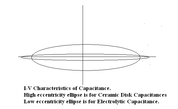
  1. CERMETS are film resistances where ceramic and metal films are used. These are also of 0.1% tolerance and zero t.c.r. Ceramic has a negative t.c.r. and Metal has positive t.c.r. Hence a proper combination of Ceramic and Metal gives zero t.c.r. These are truly precision components used in Intrumentation.
  2. Wire Wound Resistances: These are power resistances which can go up to 100W maximum power dissipation. These are green in colour and robust in appearance.
  3. Variable Resistances: These are carbon track potentiometers and Rheostats. Carbon track resistances are used in Electronics Lab and are of less than 1W rating. Rheostats are used in Electrical Engineering Labs and can go up to 1000W. Rheostat are made of Cu/Ni or Ni/Cr alloy of low t.c.r.. In Carbon Track Potentiometer there is a carbon track on which a wiper sweeps from one end to the other. The two terminals connected to the two ends of the carbon track give a fixed resistance while the resistance between one of the end terminals and the terminal connected to the wiper is a variable resistance.

Capacitor:

  1. Ceramic Disc Capacitances:

These are the cheapest and most widely used capacitances. The values are given as 103. 103 means 10×10 3 pF (pF is called PUF). This is 10 -8 F=0.01μF.

  1. Paper/Mica Capacitances.

  2. Polyesterene Capacitances: These are low loss angle high quality capacitances.
  3. Electrolytic Capacitances: The large magnitude of capacitances more than 1μF up to 1000μF can be realized by electrolytic Capacitances. These are polar capacitances. The polarity of the DC Voltage applied should be correct so that the electrolyte between the electrodes act like dielectric. If the polarity is reversed then it becomes a conductor.
  4. Variable Capacitances: Gang Capacitances- these are air-gap capacitances used as tuning capacitances in Radio-Broadcast Receivers. Trimmers and Padders are used for alignment of the tuned circuits in Radio Receivers.

Get Jobilize Job Search Mobile App in your pocket Now!

Get it on Google Play Download on the App Store Now


Source:  OpenStax, Solid state physics and devices-the harbinger of third wave of civilization. OpenStax CNX. Sep 15, 2014 Download for free at http://legacy.cnx.org/content/col11170/1.89
Google Play and the Google Play logo are trademarks of Google Inc.

Notification Switch

Would you like to follow the 'Solid state physics and devices-the harbinger of third wave of civilization' conversation and receive update notifications?

Ask