

| << Chapter < Page | Chapter >> Page > |
This paper will discuss the different elements of our functioning force sensor. These include: the components thereof, sensor physics, accuracy of the device, and possible applications; both present and future.
Keywords
Unity Gain Buffer (UGB), Liquid Chrystal Display (LCD), Force Sensor (FSR).
The purpose of this assignment was to build a functioning sensor using the MSP430F449 microprocessor. The sensor should generate an analog to digital signal which can then be displayed on the provided LCD. Our team has constructed a functioning force sensor. The sensor consists of four elements. The first element consists of the various power supplies used to power up the different components of the device. The second element is a voltage divider network which includes a variable resistance force sensor. The third element is an op-amp which functions as a UGB. The final element consists of the MSP430F449 microprocessor and its associated LCD. Together these four elements can detect and output the magnitude of a force applied to the sensing element (see fig. 1).

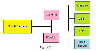
The main power source for the device is a single nine volt battery. A simple sliding on-off switch is used to connect the device to the battery when operation is desired. The force sensing voltage divider network requires a five volt supply. A wire is run from the battery to a standard five volt voltage regulator that has been soldered to the board. A separate 3.3 volt supply is required for the MSP430F449 microprocessor and its associated LCD. This is made possible by utilizing the provided 3.3 volt precision voltage regulator that was supplied with the project kit. The 3.3 volt supply also provides the rail voltages for the UGB. This configuration ensures that the maximum signal input to the microprocessor does not exceed 3.3 volts (see fig. 2).
The voltage divider network consists of the above mentioned five volt supply, a variable resistance FSR, and a 10 kilo-ohm resistor. The components are wired as shown below:

The FSR used in this device can be purchased online at sparkfun.com. The FSR is a force sensitive resistor with a square, 1.75 x 1.5" sensing area. Its resistance will vary depending on how much pressure is being applied to the sensing area; the harder the force, the lower the resistance. When no pressure is being applied to the FSR its resistance will be larger than 1MΩ [1]. The following is a detailed explanation of the inner workings of the FSR used in our device. In a nutshell the FSR is made up of two enmeshed conductors embedded in a piezosensitive conducting film. The two conductors do not make direct contact with each other. Instead the film acts as a variable resistance barrier between them. This film is a polymer matrix composed of very small conductive elements held in suspension by a non-conducting substance [1]. The sensing film is compressible and elastic. This compressibility allows the position of the conducting elements to change when under the pressure of a load. As the load is applied some of the conducting elements butt up against the surfaces of the enmeshed conductors. In addition, the conducting particles themselves are moved closer together as a result of the downward force. These actions allow the resistance of the sensor as a whole (R ab ) to decrease under an applied load. Because the film is elastic the conducting film reverts back to its original position and shape when the load is removed. Because there are no semiconductors inside the sensor it is generally impervious to damage by most electromagnetic fields. It should be noted that forces capable of stressing the film or either of the conductors beyond the elastic range can cause irreversible damage to the sensor.
Notification Switch
Would you like to follow the 'Eel3111 force sensor group july 2010' conversation and receive update notifications?

|
|

|
|

|
|

|
|

|
|

|
|

|
|

|
|

|
|

|