

| << Chapter < Page | Chapter >> Page > |
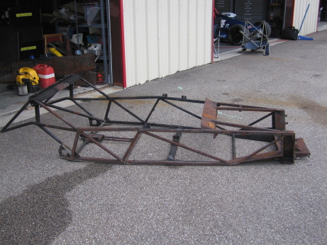
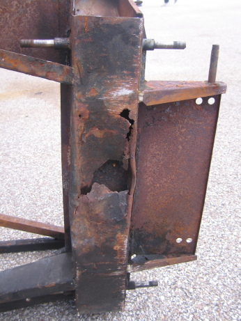
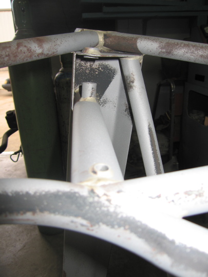
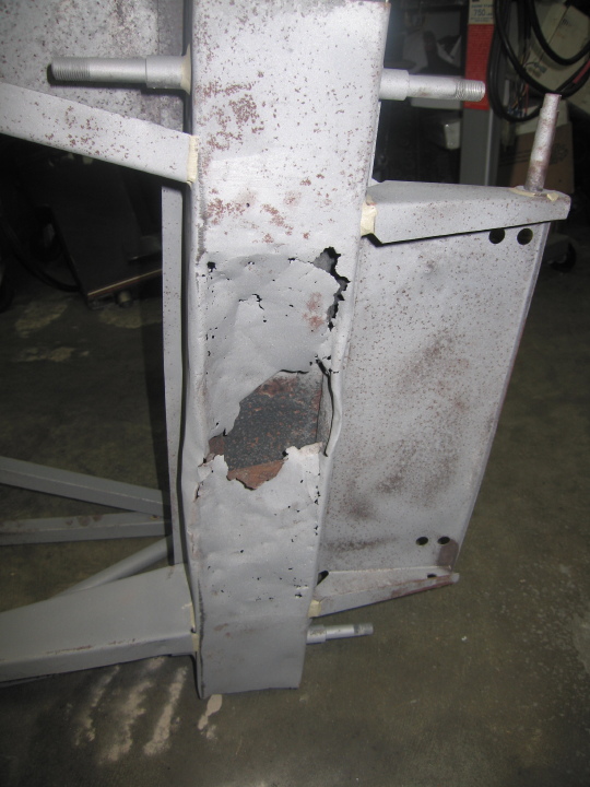
The Seven S4 (Type 60) chassis is actually comprised of a tubular structure reinforced by two sheet steel side panels that are spot-welded along the side and underside of the chassis. Once the chassis was stripped it was clear that here were signs of corrosion of the side lower tube below the sheet panel. Removal of both panels ( [link] ) showed only surface corrosion at this location. However, one of the upper side tubes was significantly corroded in the region of the engine bay and this had led to a 1 / 2 ” length hole. In addition to chassis lower tube the front box section had corroded resulting in the destruction of a significant portion of the lower half ( [link] ).
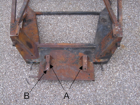
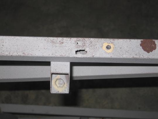
Three of the four bolts holding the two steering rack clamps were readily loosened; however, the last (forward right hand side) sheered-off ( [link] ) and will have to be drilled out.
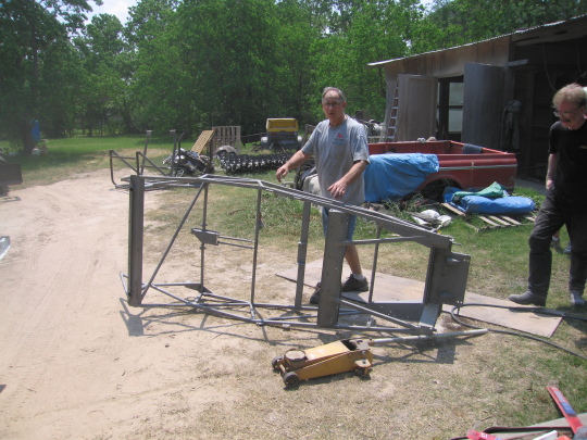
All chassis repairs were undertaken by Lucas Racing and Restoration (Houston, TX). In order to ascertain whether there was any additional damage hidden by corrosion, the chassis was cleaned by Custom Coatings (Cypress, TX) using media (alumina) blasting ( [link] ). Importantly, the bronze welding used on the chassis showed no sign of damage due to either age or the fire ( [link] ).
As expected the front box section will have to be replaced ( [link] ). Happily, the only damage due to corrosion in the steel tubing appeared to be in the upper right side tube, the lower left and right sides. In addition, it was found that one of the upper engine cross members was cracked.
The first issue was to make a jig to ensure that the chassis frame remains straight during repair. As such it was found that there was a slight bend in the chassis frame that will be straightened during repair. The small sections of the right side upper and lower tubes were repaired by cutting out a small area from the damaged face ( [link] ) and welding in a replacement section ( [link] and [link] ). A similar process was used for the engine upper member ( [link] ).
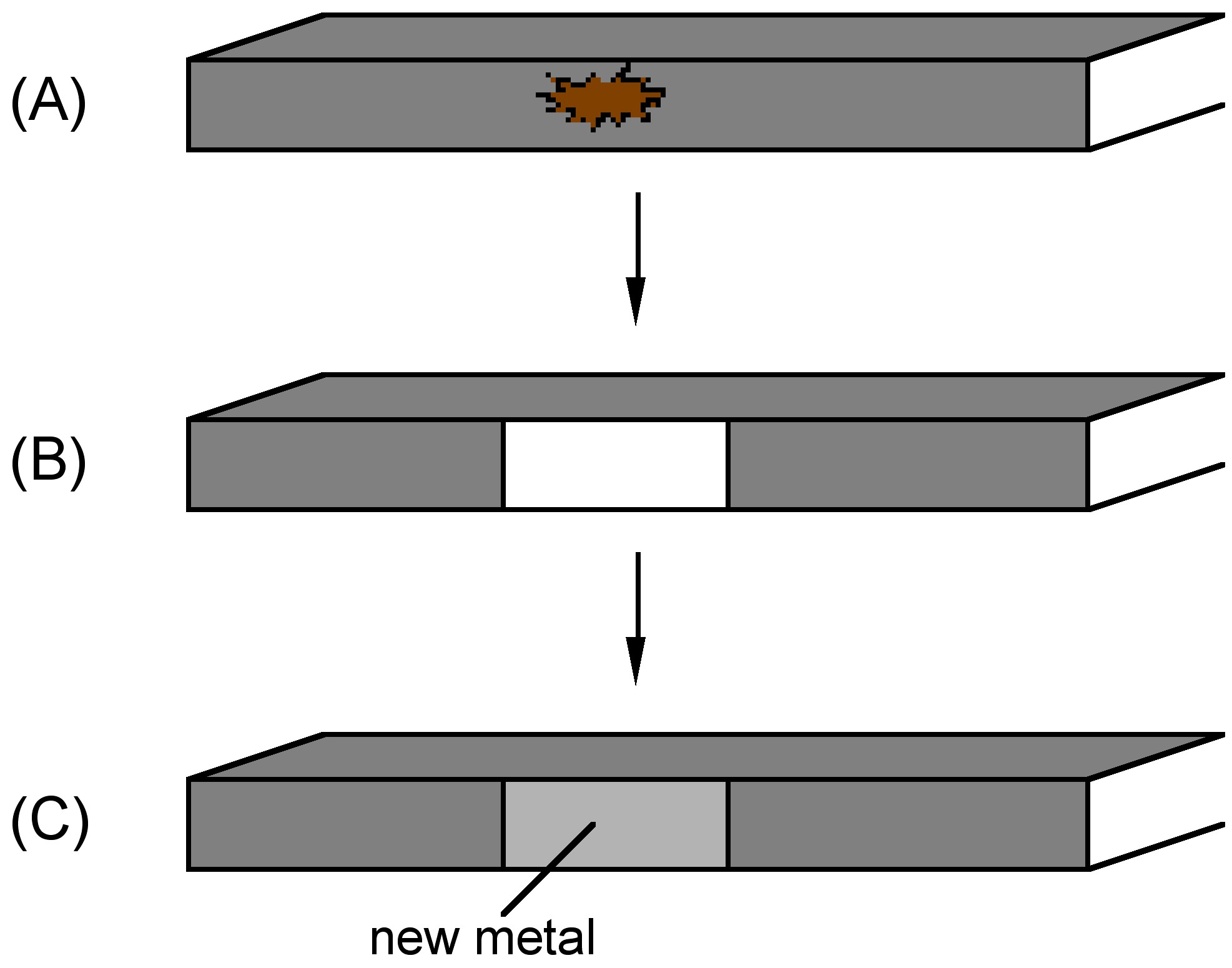
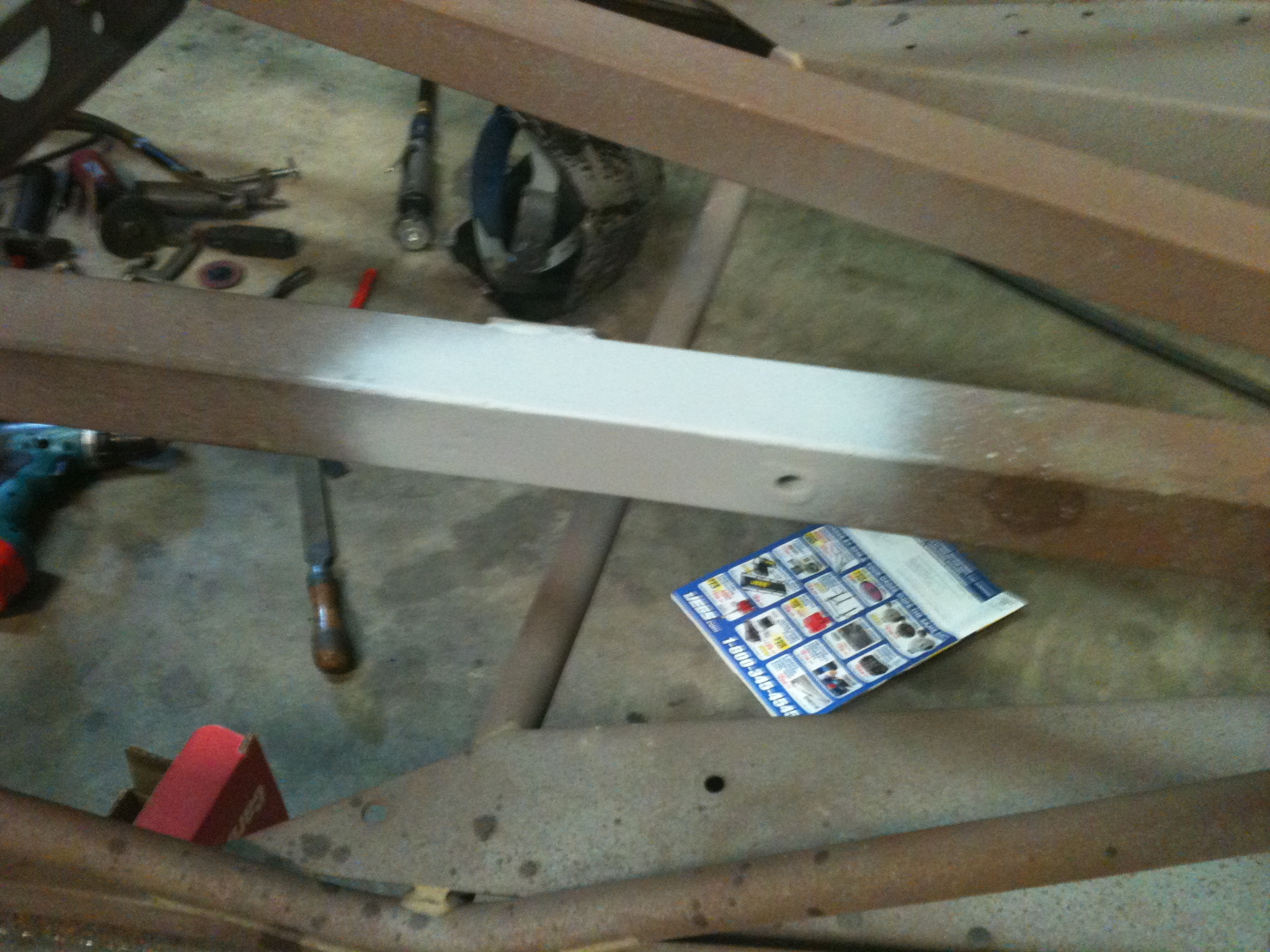
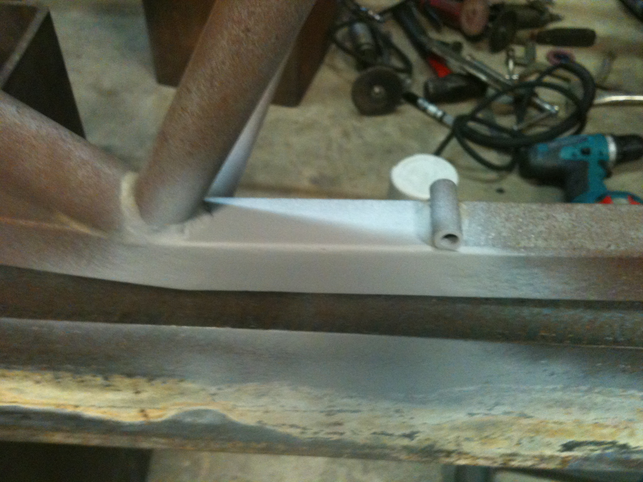
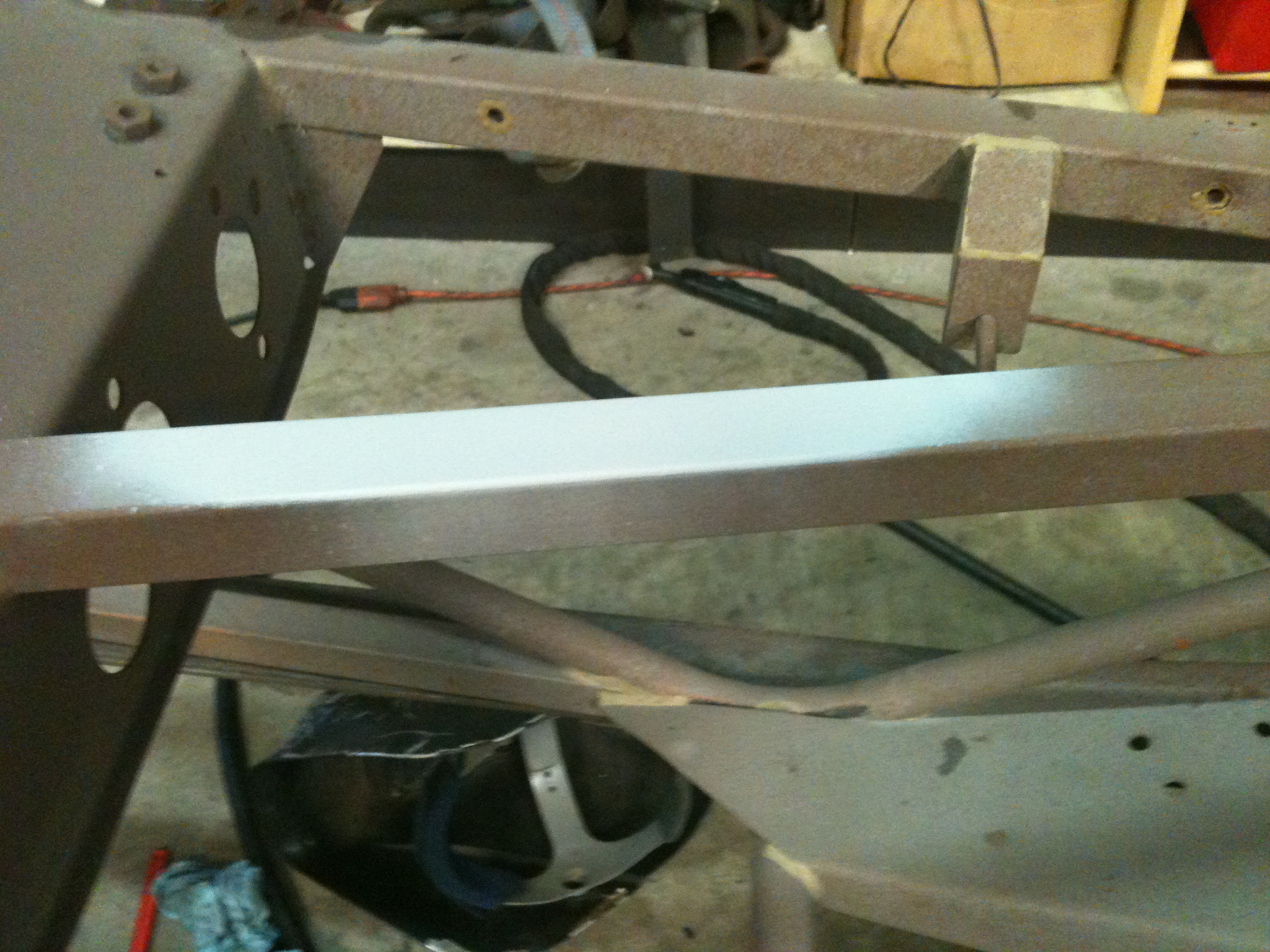
The lower left side required two separate sections to be replaced either side of one of the body-to-chassis threaded bobbins ( [link] ). One small section was removed in a similar manner to done for the upper tubes ( [link] ) then a new piece of steel welded in-place. The second, larger, section was cut out completely rather than just one face of the tube. Furthermore, it was cut at an angle rather than at 90° to the tube ( [link] ) in order to provide larger welding area. The finished section is shown in [link] .
Notification Switch
Would you like to follow the 'Lotus seven s4 (type 60): design, restoration, and maintenance' conversation and receive update notifications?

|
|

|
|

|
|

|
|

|
|

|
|

|
|

|
|

|
|

|