Figure 9.2 Torque-speed characteristic of a single-phase induction motor
(a) on the basis of constant forward and backward flux waves,
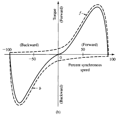
(b) taking into account changes in the flux waves.
When the rotor is in motion, the component rotor currents induced by the backward field are greater than at standstill, and their power factor is lower. Their mmf, which opposes that of the stator current, results in a reduction of the backward flux wave. Conversely, the magnetic effect of the component currents induced by the forward field is less than at standstill because the rotor currents are less and their power factor is higher. As speed increases, therefore, the forward flux wave increases while the backward flux wave decreases. The sum of these flux waves must remain roughly constant since it must induce the stator counter emf, which is approximately constant if the stator leakage-impedance voltage drop is small.
Hence, with the rotor in motion, the torque of the forward field is greater and that of the backward field less than in Fig. 9.2a, the true situation being about that shown in Fig. 9.2b. In the normal running region at a few percent slip, the forward field is several times greater than the backward field, and the flux wave does not differ greatly from the constant-amplitude revolving field in the air gap of a balanced polyphase motor.
In the normal running region, therefore, the torque-speed characteristic of a single-phase motor is not too greatly inferior to that of a polyphase motor having the same rotor and operating with the same maximum air-gap flux density.
In addition to the torques shown in Fig. 9.2, double-stator-frequency torque pulsations are produced by the interactions of the oppositely rotating flux and mmf waves which rotate past each other at twice synchronous speed. These interactions produce no average torque, but they tend to make the motor noisier than a polyphase motor.
9.2 STARTING AND RUNNING
PERFORMANCE OF SINGLE-PHASE
INDUCTION AND SYNCHRONOUS MOTORS
Single-phase induction motors are classified in accordance with their starting methods and are usually referred to by names descriptive of these methods.
Split-phase motors have two stator windings, a main winding (also referred to as the run winding) which we will refer to with the subscript 'main' and an auxiliary winding (also referred to as the start winding) which we will refer to with the subscript 'aux'. As in a two-phase motor, the axes of these windings are displaced 90 electrical degrees in space, and they are connected as shown in Fig. 9.3a. The auxiliary winding has a higher resistance-to-reactance ratio than the main winding, with the result that the two currents will be out of phase, as indicated in the phasor diagram of Fig. 9.3b, which is representative of conditions at starting. Since the auxiliary-winding current
leads the main-winding current
, the stator field first reaches a maximum along the axis of the auxiliary winding and then somewhat later in time reaches a maximum along the axis of the main winding.
The winding currents are equivalent to unbalanced two-phase currents, and the motor is equivalent to an unbalanced two-phase motor. The result is a rotating stator field which causes the motor to start. After the motor starts, the auxiliary winding is disconnected, usually by means of a centrifugal switch that operates at about 75 percent of synchronous speed. The simple way to obtain the high resistance-to-reactance ratio for the auxiliary winding is to wind it with smaller wire than the main winding, a permissible procedure because this winding operates only during starting. Its reactance can be reduced somewhat by placing it in the tops of the slots. A typical torque-speed characteristic for such a motor is shown in Fig. 9.3c.
Split-phase motors have moderate starting torque with low starting current. Typical applications include fans, blowers, centrifugal pumps, and office equipment. Typical ratings are 50 to 500 watts; in this range they are the lowest-cost motors available.