<< Chapter < Page Chapter >> Page >

SCR = O f ' O f ' ' size 12{ ital "SCR"= { {O { {f}} sup { ' }} over {O { {f}} sup { '' }} } } {} (5.37)

SCR = AFNL AFSC size 12{ ital "SCR"= { { ital "AFNL"} over { ital "AFSC"} } } {} (5.38)

Figure 5.13 Typical form of short-circuit load loss and stray load-loss curves.

R T R T = 234 . 5 + T 234 . 5 + t size 12{ { {R rSub { size 8{T} } } over {R rSub { size 8{T} } } } = { {"234" "." 5+T} over {"234" "." 5+t} } } {} (5.39)

R a , eff = short circuit load loss ( short circuit armature current ) 2 size 12{R rSub { size 8{a, ital "eff"} } = { {"short" - "circuit load loss"} over { \( "short" - "circuit armature current" \) rSup { size 8{2} } } } } {} (5.40)

§5.5 Steady-State Operating Characteristics

Figure 5.14 Characteristic form of synchronous-generator compounding curves.

Figure 5.15 Capability curves of an 0.85 power factor, 0.80 short-circuit ratio,

hydrogen-cooled turbine generator. Base MVA is rated MVA at 0.5 psig hydrogen.

Apprent power = P 2 + Q 2 = V a I a size 12{"Apprent power"= sqrt {P rSup { size 8{2} } +Q rSup { size 8{2} } } =V rSub { size 8{a} } I rSub { size 8{a} } } {}

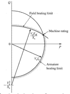
Figure 5.16 Construction used for the derivation of a synchronous generator capability curve.

P jQ = V ˆ a + jX s I ˆ a size 12{P - ital "jQ"= { hat {V}} rSub { size 8{a} } + ital "jX" rSub { size 8{s} } { hat {I}} rSub { size 8{a} } } {} (5.41)

E ˆ af = V ˆ a + jX s I ˆ a size 12{ { hat {E}} rSub { size 8{ ital "af"} } = { hat {V}} rSub { size 8{a} } + ital "jX" rSub { size 8{s} } { hat {I}} rSub { size 8{a} } } {} (5.42)

P 2 + ( Q + V a 2 X s ) 2 = ( V a E af X s ) 2 size 12{P rSup { size 8{2} } + \( Q+ { {V rSub { size 8{a} } rSup { size 8{2} } } over {X rSub { size 8{s} } } } \) rSup { size 8{2} } = \( { {V rSub { size 8{a} } E rSub { size 8{ ital "af"} } } over {X rSub { size 8{s} } } } \) rSup { size 8{2} } } {} (5.43)

Figure 5.17 Typical form of synchronous-generator V curves.

§5.6 Effects of Salient Poles; Introduction to Direct-And

Quadrature-Axis Theory

§5.6.1 Flux and MMF Waves

Figure 5.18 Direct-axis air-gap fluxes in a salient-pole synchronous machine.

E 3, a = 2 V 3 cos ( e t + φ 3 ) size 12{E rSub { size 8{3,a} } = sqrt {2} V rSub { size 8{3} } "cos" \( 3ω rSub { size 8{e} } t+φ rSub { size 8{3} } \) } {} (5.44)

E 3, b = 2 V 3 cos ( 3 ( ω e 120 o ) + φ 3 ) = 2 V 3 cos ( e t + φ 3 ) size 12{E rSub { size 8{3,b} } = sqrt {2} V rSub { size 8{3} } "cos" \( 3 \( ω rSub { size 8{e} } - "120" rSup { size 8{o} } \) +φ rSub { size 8{3} } \) = sqrt {2} V rSub { size 8{3} } "cos" \( 3ω rSub { size 8{e} } t+φ rSub { size 8{3} } \) } {} (5.45)

E 3, c = 2 V 3 cos ( 3 ( ω e t 120 o ) + φ 3 ) = 2 V 3 cos ( e t + φ 3 ) size 12{E rSub { size 8{3,c} } = sqrt {2} V rSub { size 8{3} } "cos" \( 3 \( ω rSub { size 8{e} } t - "120" rSup { size 8{o} } \) +φ rSub { size 8{3} } \) = sqrt {2} V rSub { size 8{3} } "cos" \( 3ω rSub { size 8{e} } t+φ rSub { size 8{3} } \) } {} (5.45)

Figure 5.19 Quadrature-axis air-gap fluxes in a salient-pole synchronous machine.

Figure 5.20 Phasor diagram of a salient-pole synchronous generator.

§5.6.2 Phasor Diagrams for Salient-Pole Machines

Figure 5.21 Phasor diagram for a synchronous generator showing

the relationship between the voltages and the currents.

X d = X al + X ϕd size 12{X rSub { size 8{d} } =X rSub { size 8{ ital "al"} } +X rSub { size 8{ϕd} } } {} (5.46)

X q = X al + X ϕq size 12{X rSub { size 8{q} } =X rSub { size 8{ ital "al"} } +X rSub { size 8{ϕq} } } {} (5.47)

Figure 5.22 Relationships between component voltages in a phasor diagram.

o ' a ' oa = b ' a ' ba size 12{ { { { {o}} sup { ' } { {a}} sup { ' }} over { ital "oa"} } = { { { {b}} sup { ' } { {a}} sup { ' }} over { ital "ba"} } } {} (5.48)

o ' a ' = ( b ' a ' ba ) oa = I ˆ q X q I ˆ q I ˆ a = X q I ˆ a size 12{ { {o}} sup { ' } { {a}} sup { ' }= \( { { { {b}} sup { ' } { {a}} sup { ' }} over { ital "ba"} } \) ital "oa"= { { \lline { hat {I}} rSub { size 8{q} } \lline X rSub { size 8{q} } } over { \lline { hat {I}} rSub { size 8{q} } \lline } } \lline { hat {I}} rSub { size 8{a} } \lline =X rSub { size 8{q} } \lline { hat {I}} rSub { size 8{a} } \lline } {} (5.49)

E ˆ af = V ˆ a + R a I ˆ a + jX d I ˆ d + jX q I ˆ q size 12{ { hat {E}} rSub { size 8{ ital "af"} } = { hat {V}} rSub { size 8{a} } +R rSub { size 8{a} } { hat {I}} rSub { size 8{a} } + ital "jX" rSub { size 8{d} } { hat {I}} rSub { size 8{d} } + ital "jX" rSub { size 8{q} } { hat {I}} rSub { size 8{q} } } {} (5.50)

5.7 Power-Angle Characteristics Of Salient-Pole Machines

  • For the purposes of this discussion, it is sufficient to limit our discussion to the simple system shown in the schematic diagram of Fig.5.23a, consisting of a salient pole synchronous machine SM connected to an infinite bus of voltage V ˆ EQ size 12{ { hat {V}} rSub { size 8{ ital "EQ"} } } {} through a series impedance of reactance X EQ size 12{X rSub { size 8{ ital "EQ"} } } {} . Resistance will be neglected because it is usually small. Consider that the synchronous machine is acting as a generator. The phasor diagram is shown by the solid-line phasors in Fig.5.23b. The dashed phasors show the external reactance drop resolved into components due to I ˆ d size 12{ { hat {I}} rSub { size 8{d} } } {} and I ˆ q size 12{ { hat {I}} rSub { size 8{q} } } {} . The effect of the external impedance is merely to add its reactance to the reactances of the machine; the total values of the reactance between the excitation voltage E ˆ af size 12{ { hat {E}} rSub { size 8{ ital "af"} } } {} and the bus voltage V ˆ EQ size 12{ { hat {V}} rSub { size 8{ ital "EQ"} } } {} is therefore

X dT = X d + X EQ size 12{X rSub { size 8{ ital "dT"} } =X rSub { size 8{d} } +X rSub { size 8{ ital "EQ"} } } {} (5.50)

X qT = X q + X EQ size 12{X rSub { size 8{ ital "qT"} } =X rSub { size 8{q} } +X rSub { size 8{ ital "EQ"} } } {} (5.51)

  • If the bus voltage V ˆ EQ size 12{ { hat {V}} rSub { size 8{ ital "EQ"} } } {} is resolved into components its direct-axis component V d = V EQ sin δ size 12{V rSub { size 8{d} } =V rSub { size 8{ ital "EQ"} } "sin"δ} {} and quadrature-axis component V q = V EQ cos δ size 12{V rSub { size 8{q} } =V rSub { size 8{ ital "EQ"} } "cos"δ} {} in phase with I ˆ d size 12{ { hat {I}} rSub { size 8{d} } } {} and I ˆ q size 12{ { hat {I}} rSub { size 8{q} } } {} , respectively, the power P delivered to the bus per phase (or in per unit) is

P = I d V d + I q V q = I d V EQ sin δ + I q V EQ cos δ size 12{P=I rSub { size 8{d} } V rSub { size 8{d} } +I rSub { size 8{q} } V rSub { size 8{q} } =I rSub { size 8{d} } V rSub { size 8{ ital "EQ"} } "sin"δ+I rSub { size 8{q} } V rSub { size 8{ ital "EQ"} } "cos"δ} {} (5.52)

I d = E af V EQ cos δ X dT size 12{I rSub { size 8{d} } = { {E rSub { size 8{ ital "af"} } - V rSub { size 8{ ital "EQ"} } "cos"δ} over {X rSub { size 8{ ital "dT"} } } } } {} (5.53)

I q = V EQ sin δ X qT size 12{I rSub { size 8{q} } = { {V rSub { size 8{ ital "EQ"} } "sin"δ} over {X rSub { size 8{ ital "qT"} } } } } {} (5.54)

P = E af V EQ X dT sin δ + V EQ 2 ( X dT X qT ) 2X dT X qT sin size 12{P= { {E rSub { size 8{ ital "af"} } V rSub { size 8{ ital "EQ"} } } over {X rSub { size 8{ ital "dT"} } } } "sin"δ+ { {V rSub { size 8{ ital "EQ"} } rSup { size 8{2} } \( X rSub { size 8{ ital "dT"} } - X rSub { size 8{ ital "qT"} } \) } over {2X rSub { size 8{ ital "dT"} } X rSub { size 8{ ital "qT"} } } } "sin"2δ} {} (5.55)

Figure 5.23 Salient-pole synchronous machine and series impedance: (a) single-line diagram and (b) phasor diagram.

Figure 5.24 Power-angle characteristic of a salient-pole synchronous machine showing the fundamental component due to field excitation and the second-harmonic component due to reluctance torque.

Questions & Answers

what is phylogeny
Odigie Reply
evolutionary history and relationship of an organism or group of organisms
AI-Robot
ok
Deng
what is biology
Hajah Reply
the study of living organisms and their interactions with one another and their environments
AI-Robot
what is biology
Victoria Reply
HOW CAN MAN ORGAN FUNCTION
Alfred Reply
the diagram of the digestive system
Assiatu Reply
allimentary cannel
Ogenrwot
How does twins formed
William Reply
They formed in two ways first when one sperm and one egg are splited by mitosis or two sperm and two eggs join together
Oluwatobi
what is genetics
Josephine Reply
Genetics is the study of heredity
Misack
how does twins formed?
Misack
What is manual
Hassan Reply
discuss biological phenomenon and provide pieces of evidence to show that it was responsible for the formation of eukaryotic organelles
Joseph Reply
what is biology
Yousuf Reply
the study of living organisms and their interactions with one another and their environment.
Wine
discuss the biological phenomenon and provide pieces of evidence to show that it was responsible for the formation of eukaryotic organelles in an essay form
Joseph Reply
what is the blood cells
Shaker Reply
list any five characteristics of the blood cells
Shaker
lack electricity and its more savely than electronic microscope because its naturally by using of light
Abdullahi Reply
advantage of electronic microscope is easily and clearly while disadvantage is dangerous because its electronic. advantage of light microscope is savely and naturally by sun while disadvantage is not easily,means its not sharp and not clear
Abdullahi
cell theory state that every organisms composed of one or more cell,cell is the basic unit of life
Abdullahi
is like gone fail us
DENG
cells is the basic structure and functions of all living things
Ramadan
What is classification
ISCONT Reply
is organisms that are similar into groups called tara
Yamosa
in what situation (s) would be the use of a scanning electron microscope be ideal and why?
Kenna Reply
A scanning electron microscope (SEM) is ideal for situations requiring high-resolution imaging of surfaces. It is commonly used in materials science, biology, and geology to examine the topography and composition of samples at a nanoscale level. SEM is particularly useful for studying fine details,
Hilary
Got questions? Join the online conversation and get instant answers!
Jobilize.com Reply

Get Jobilize Job Search Mobile App in your pocket Now!

Get it on Google Play Download on the App Store Now


Source:  OpenStax, Electrical machines. OpenStax CNX. Jul 29, 2009 Download for free at http://cnx.org/content/col10767/1.1
Google Play and the Google Play logo are trademarks of Google Inc.

Notification Switch

Would you like to follow the 'Electrical machines' conversation and receive update notifications?

Ask